Design method for LNG leakage collection tray

A design method and collection tray technology, applied in the design field of LNG leakage collection trays, can solve the problems of not considering the specificity of collection protection points, over-conservation, equipment structural load, etc.

Active Publication Date: 2016-10-26
BC P INC CHINA NAT PETROLEUM CORP +1
View PDF1 Cites 2 Cited by
  • Summary
  • Abstract
  • Description
  • Claims
  • Application Information

AI Technical Summary

Problems solved by technology

However, for the collection tray installed in the actual process device, the design difficulty lies in that the collection process is a dynamic process, and the potential leakage is different according to the operating conditions of the protection equipment corresponding to the collection tray. The collection pipe is exported, and the low temperature effect of LNG determines that the liquid pool formed in the collection plate will undergo a significant evaporation effect, so the whole process is a highly coupled dynamic process of heat and mass
The current conventional practice of collection trays often simply refers to the existing project experience for the structural design of the collection tray, without considering the specificity of the collection protection point, or ignoring the effects of various factors in the collection process, failing to effectively realize the collection protection purpose, or too conservative, higher and larger collection trays are installed in each protection area, which will cause a large load on the equipment structure and bring difficulties to the maintenance and operation of the device

Method used


Image

  • Design method for LNG leakage collection tray
  • Design method for LNG leakage collection tray
  • Design method for LNG leakage collection tray

Examples


Embodiment Construction

[0060] The following will clearly and completely describe the technical solutions in the embodiments of the present invention with reference to the accompanying drawings in the embodiments of the present invention. Obviously, the described embodiments are only some, not all, embodiments of the present invention. Based on the embodiments of the present invention, all other embodiments obtained by persons of ordinary skill in the art without making creative efforts belong to the protection scope of the present invention.

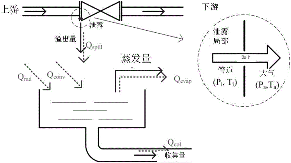
[0061] The physical process of LNG leakage collection such as figure 1 As shown in , when the integrity of valves, flanges, pipe fittings, etc. is damaged, because the LNG delivery pressure in the pipeline is higher than the external ambient pressure, LNG leaks from the system to the collection pan. Part of the LNG entering the collection pan flows into the collection main pipe along the collection branch pipe and leads to the collection pool, part of it evapo...


PUM


Abstract

The invention discloses a design method for an LNG leakage collection tray. The method comprises the steps that an input-output dynamic relation model of LNG leakage in the collection tray is established, an initial value is assigned to the model, and recursive calling is conducted according to a set step length, so that a curve about time-based changing of the mass of LNG stored in the collection tray can be obtained; and according to the curve, a bottom disk area of the collection tray, a cofferdam height and a sectional area of a collection pipe connected to the collection tray can be determined. The curve obeys the changing rules that when a liquid level of the LNG in the collection tray reaches a certain height, the continuous leakage under an original scale does not cause further increase of the LNG liquid level; and with weakening and stopping of the leakage, collection and evaporation effects can be continued, and the LNG liquid level in the collection tray gradually decreases till the liquid level approaches zero.

Description

technical field [0001] The invention relates to the technical field of liquefied natural gas, in particular to a design method of an LNG leakage collecting tray. Background technique [0002] According to the requirements of domestic and foreign liquefied natural gas (LNG) onshore facility design specifications (GB50183\NFPA 59A\EN1473, etc.), it is necessary to design an LNG leakage collection system at the LNG station to collect the accidentally scattered LNG in the accident state and send it to the designated area. Safe and centralized treatment is carried out to avoid low temperature damage caused by low-temperature LNG flowing around, and the risk of fire and explosion caused by flammable and explosive vapor clouds formed after gasification. [0003] The LNG leakage collection pan is an important part of the collection system. Both experimental and simulation results show that the reasonable setting of the collection pan can effectively reduce the gasification of leaked...

Claims


Application Information

Patent Timeline
Patent Type & Authority Applications(China)
IPC IPC(8): G06F17/50
CPCG06F30/17G06F30/367
Inventor 贺丁舒小芹扈洁琼赵欣赵晓静黄会伟
Owner BC P INC CHINA NAT PETROLEUM CORP
Why Eureka
Try Eureka