Dangerous rock displacement monitoring method based on image modeling

A displacement monitoring and image modeling technology, applied in image enhancement, image analysis, image data processing, etc., can solve the problems of motion interference, slow processing time, and high monitoring costs, to overcome changes in illumination, reduce monitoring costs, and solve problems. difficult effect

Inactive Publication Date: 2016-10-26
CHINA MERCHANTS CHONGQING COMM RES & DESIGN INST
View PDF8 Cites 4 Cited by
  • Summary
  • Abstract
  • Description
  • Claims
  • Application Information

AI Technical Summary

Problems solved by technology

However, these dangerous rock safety monitoring methods often require the help of relatively expensive special detection facilities, or the assistance of more complex address survey methods, the monitoring cost is high, the processing time is slow, and it is difficult to achieve continuous real-time monitoring
[0005] The more commonly used technical means for continuous real-time monitoring is the dangerous rock displacement monitoring method based on computer image processing technology. Object detection, to realize real-time monitoring of the displacement of dangerous rocks, among which the more commonly used detection methods for moving objects are mainly background difference method and frame difference method; The influence of image chromaticity and brightness, and the inter-frame difference method can overcome the influence of illumination changes and climate changes to a certain extent, but it is vulnerable to non-dangerous rock moving objects such as swaying leaves and passing pedestrians. motion interference
Therefore, the monitoring accuracy of the dangerous rock displacement monitoring method based on computer image processing technology in the prior art is relatively limited, and the misjudgment rate is high, so it is difficult to be well applied to the actual dangerous rock safety monitoring technology.

Method used


Image

  • Dangerous rock displacement monitoring method based on image modeling
  • Dangerous rock displacement monitoring method based on image modeling

Examples


Embodiment Construction

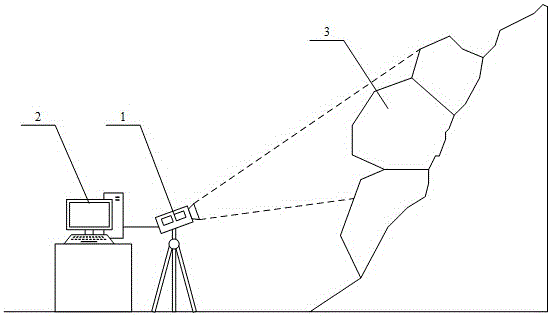
[0036] The present invention provides a dangerous rock displacement monitoring method based on image modeling, which is based on computer image processing and modeling matching technology, and its monitoring implementation scenarios are as follows figure 1 As shown, the camera device 1 is used to collect images and monitor the dangerous rock area to be observed, and the dangerous rock mass 3 to be observed in the dangerous rock area is used as the target, and the computer device 2 is used to obtain the monitoring image of the camera device 1 for moving object detection, and then Realize real-time monitoring of the displacement of dangerous rocks. However, in the dangerous rock displacement monitoring method based on image modeling of the present invention, it is necessary to adopt a new image processing scheme to overcome the influence of illumination changes, climate changes, and movement interference of non-dangerous rock moving objects, so as to improve the safety of dangerous...


PUM


Abstract

The invention provides a dangerous rock displacement monitoring method based on image modeling. The method based on computer image processing and modeling matching technologies can perform all-weather real-time monitoring on a displacement condition of a dangerous rock in a to-be-observed dangerous rock area, the method does not need the aid of a relatively expensive special detection facility and also the help of a relatively complex address exploration and survey method, and the method reduces monitoring cost and improves a scheme for monitoring a dangerous rock displacement through computer image processing. Through combinations with background image model and a scheme of matching processing for a monitored image, the method can effectively overcome influences of illumination and climate changes and a motion interference of a non-dangerous rock moving object; and, through a combination with a multi-matching determination mechanism, the method ensures accuracy of a displacement monitoring result of the to-be-observed dangerous rock, the method effectively solves the problems of difficult implementation, high monitoring cost and limited monitoring accuracy of real-time monitoring of dangerous rock safety in the prior art, and the method can be applied to an actual dangerous rock safety monitoring technology well.

Description

technical field [0001] The invention relates to the technical fields of dangerous rock protection and control technology and computer image processing, in particular to a dangerous rock displacement monitoring method based on image modeling. Background technique [0002] Dangerous rock is a potential collapse body, which is a relatively common structure in the field of geotechnical engineering. The main basis for its identification is: the location has a large height difference, or the slope is an isolated and steep mountain mouth, and there is a huge empty surface in front of the slope. The slope is concave and steep; cracks are developed in the slope body, the rock mass structure is incomplete, and there are a large number of cracks or weak zones that are consistent with or parallel to the slope; the development of collapses at the foot of the slope indicates that collapse activities have occurred; Cracks appear and expand continuously; rock mass creeps and rocks fall; the...

Claims


Application Information

Patent Timeline
Patent Type & Authority Applications(China)
IPC IPC(8): G06T7/00
CPCG06T2207/10016G06T2207/30184G06T2207/30232
Inventor 黄河阎宗岭徐建强张小松李聪王扬杜孟秦熊远维
Owner CHINA MERCHANTS CHONGQING COMM RES & DESIGN INST
Why Eureka
Try Eureka