
High pressure exhausting silencing apparatus

A noise reduction device and high-voltage technology, which is applied in the direction of sound-emitting devices and instruments, can solve problems such as difficult control, strong air noise, and complex structure, and achieve the goal of reducing audible noise, reducing air noise, and eliminating air noise Effect

Active Publication Date: 2016-10-26
中国船舶重工集团公司第七〇二研究所
View PDF7 Cites 8 Cited by
  • Summary
  • Abstract
  • Description
  • Claims
  • Application Information

AI Technical Summary

Problems solved by technology

The throttling control of the throttling decompression muffler mainly adopts the principle of sudden expansion throttling. This method is relatively simple, but because the gas flow velocity in a small cross-section and small chamber reaches the speed of sound and supersonic, the gas in high-speed movement It is easy to produce a high degree of inhomogeneity, which in turn will generate strong air noise, so it is difficult for this type of muffler to control the high vibration level and high noise; the small hole injection type muffler shifts the spectrum of the exhaust noise to the human ear through small holes In the inaudible high-frequency area, this kind of noise reduction method has a certain noise reduction effect, but it has a relatively large limit on the air intake pressure (generally no more than 10kg / cm2); the current exhaust muffler with composite structure is mainly multiple The combination of three parallel throttling muffler pipes, small hole injection structure, perforated pipe and filled with sound-absorbing materials, this kind of muffler has a significant noise reduction effect, but its structure is complex and bulky, subject to In the actual use process, there are many restrictions on the environment, and the stability is relatively low

Method used


Image

  • High pressure exhausting silencing apparatus
  • High pressure exhausting silencing apparatus
  • High pressure exhausting silencing apparatus

Examples


Embodiment Construction

[0030] The specific implementation manner of the present invention will be described below in conjunction with the accompanying drawings.

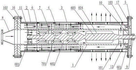
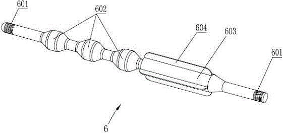
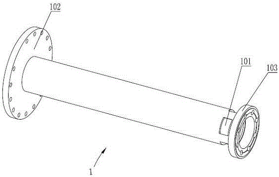
[0031] See figure 1 , figure 2 , image 3 , the present invention includes a throttling tube 1, a perforated inner tube 2 and a perforated outer tube 3 that are sequentially socketed from the inside to the outside, and the three are coaxially socketed, and the perforated inner tube 2 and the perforated outer tube 3 are provided with a plurality of diameters To the through microhole 4, one end of the throttle tube 1 is the air intake end, and the other end of the throttle tube 1 is provided with a radial through hole 101; The intake end is fixedly connected, the other ends of the throttle tube 1, the perforated inner tube 2 and the perforated outer tube 3 are all fixedly connected to the cover plate 5, the outer wall of the throttle tube 1 and the inner wall of the perforated inner tube 2, and the perforated inner tube 2 A cavity for ga...


PUM


Abstract

Provided is a high pressure exhausting silencing apparatus, comprising a throttle pipe, a perforating inner pipe and a perforating outer pipe which are successively in coaxial cup joint from inside to outside. One end of the throttle pipe is used for air inflow, and the other end is provided with a radial through hole. The perforating inner pipe and the perforating outer pipe both have one end fixedly connected to the air inflow end of the throttle pipe; the throttle pipe, the perforating inner pipe and the perforating outer pipe all have the other end fixedly connected to a cover plate; a cavity for gas flow is respectively arranged between the outer wall of the throttle pipe and the inner wall of the perforating inner pipe, and between the outer wall of the perforating inner pipe and the inner wall of the perforating outer pipe; a coaxially arranged throttle lever is fixedly supported in the throttle pipe, and is provided with at least one projecting throttle joint; the periphery of the throttle lever is sleeved by a throttle sleeve which is axially limited in the throttle pipe; the external diameter of the throttle sleeve is the same with the internal diameter of the throttle pipe; the inner wall of the throttle sleeve corresponding to the throttle lever segment in front of the throttle joint is a flange; an airflow channel is formed between the inner wall of the throttle sleeve and the outer wall of the throttle lever. Through multistage decompression and speed reduction, the high pressure exhausting silencing apparatus can reduce and eliminate noise through high pressure exhausting.

Description

technical field [0001] The invention relates to the technical field of noise reduction and muffler devices, in particular to a high-pressure exhaust muffler device that implements noise reduction and muffler by performing multi-stage decompression and speed reduction on the basis of double-layer perforated pipes. Background technique [0002] The exhaust noise of high-pressure gas is generally produced by the unstable flow of high-speed airflow, that is, the strong turbulent noise generated when high-speed airflow is discharged from the exhaust pipe or nozzle. The turbulence noise is a typical quadrupole noise, and its radiation power is proportional to the pressure, the square of the nozzle diameter, and the eighth power of the velocity. Since the sound power of the quadrupole is closely related to the airflow velocity, reducing the flow velocity can greatly reduce the turbulence noise. [0003] At present, the main types of exhaust mufflers are throttling and decompressio...

Claims


Application Information

Patent Timeline
Patent Type & Authority Applications(China)
IPC IPC(8): G10K11/16
CPCG10K11/161
Inventor 王秋波刘忠族何涛郝夏影王锁泉黄伟稀
Owner 中国船舶重工集团公司第七〇二研究所
Learn More