Transformer installing mechanism

An installation mechanism and technology for transformers, which are applied in the directions of transformer/reactor installation/support/suspension, substations mounted on columns, etc., can solve problems affecting the structural stability of transformers, and achieve the effect of good seismic performance

Inactive Publication Date: 2016-10-26
STATE GRID SHANDONG ELECTRIC POWER CO LONGKOU POWER SUPPLY CO
View PDF4 Cites 4 Cited by
  • Summary
  • Abstract
  • Description
  • Claims
  • Application Information

AI Technical Summary

Problems solved by technology

The existing transformer installation usually does not install a buffer structure, so that the structural

Method used


Image

  • Transformer installing mechanism
  • Transformer installing mechanism

Examples


Embodiment 1

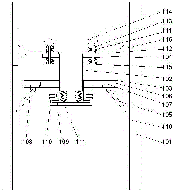
[0023] Such as figure 1 As shown, a transformer installation mechanism includes four rod bodies 101 and a transformer body 102 arranged between the rod bodies 101. A mounting plate 103 is provided at the lower end of the transformer body 102. A fixed plate 104 is arranged on the outer side of the upper end, and a strut 105 is respectively arranged on the inside of the two described rod bodies 101, and the lower ends of the described strut rods 105 are hinged on the described rod body 101, and on the lower end surface of the described mounting plate 103 Four T-shaped slots 106 are provided, and a T-shaped slide block 107 is provided at the upper end of the pole 105, and the slide block 107 can slide along the T-shaped slot 106. A threaded hole is provided on the side wall of the T-shaped groove 106, and a positioning bolt 108 is arranged in the described threaded hole, and the described positioning bolt 108 is threadedly connected in the threaded hole on the described T-shaped ...

Embodiment 2

[0028] In this embodiment, on the basis of Embodiment 1, preferably, the fixed pin 114 is threadedly connected to the vertical rod 113, and the gap between the fixed pin 114 and the upper end surface of the upper beam 112 is A high-strength spring 111 is sleeved on the pole 113 .

[0029] By adopting the high-strength spring structure, there is a certain space between the fixed pin and the upper beam, and the high-strength spring is used to buffer the force of the rod body on the upper beam, so that the lower end of the vertical rod is under the elastic force of the high-strength spring. Driven by the upper beam, it will shake relatively, so that it has better stability. At the same time, the high-strength spring is used to make the transformer body have more room to move upward.

[0030] In this embodiment, further preferably, the lower end of the vertical rod 113 runs through the upper beam 112, and a disc 115 is arranged at the end of the vertical rod 113, and the disc 115 ...

Embodiment 3

[0032] In this embodiment, in order to facilitate the installation of the upper beam, preferably, a channel steel 116 is arranged on the rod body 101, and the length direction of the channel steel 116 is parallel to the length direction of the rod body 101. The channel steel 116 is provided with at least 2 sets of through holes along the length direction of the channel steel 116, and the upper beam 112 is fixedly connected to the channel steel 116 through the bolts passing through the through holes. In this embodiment, a reinforcing rib structure may be provided under the upper beam, so that the reinforcing rib, the upper beam, and the rod body form a triangular structure of legs.

[0033] By using channel steel, it can be easily installed on the rod body, so that the two parallel end faces are used as the supporting structure for installing the upper beam, and multiple sets of bolts are used to penetrate the two opposite end faces of the channel steel to fix and fix the upper ...


PUM


Abstract

The invention discloses a transformer installing mechanism. The transformer installing mechanism comprises four rod bodies and a transformer body arranged among the rod bodies, an installing plate is arranged at the lower end of the transformer body, a fixing plate is arranged at the outer side of the upper end of the transformer body, supporting rods are arranged at the inner ends of the two rod bodies respectively, and the lower ends of the supporting rods are hinged to the rod bodies; four T-shaped grooves are formed in the lower end face of the installing plate, T-shaped sliding blocks are arranged at the upper ends of the supporting rods and can slide along the T-shaped grooves, threaded holes are formed in the side walls of the T-shaped grooves, positioning bolts are arranged in the threaded holes and connected into the threaded holes in the T-shaped grooves through threads, counter bores are formed in the sliding blocks, and the tail ends of the positioning bolts are inserted into the counter bores. Steel angles at the inner sides of the installing plate structure are adopted to limit the position of a transformer, and the transformer installing mechanism has higher anti-seismic performance.

Description

technical field [0001] The invention relates to a transformer installation mechanism. Background technique [0002] The transformer is usually fixedly installed on the utility pole, and it is relatively suspended in the middle of the utility pole by using multiple fixed brackets. The existing transformer installation usually does not install a buffer structure, so that the structural stability of the transformer is easily affected when the utility pole is damaged or subjected to vibration. Contents of the invention [0003] The purpose of the present invention is to provide a transformer installation mechanism, which can improve the problems existing in the prior art. By using the angle steel inside the installation plate structure, the position of the transformer can be limited, and at the same time, it has better seismic performance. [0004] The present invention is realized through the following technical solutions: [0005] A transformer installation mechanism, comp...

Claims


Application Information

Patent Timeline
IPC IPC(8): H01F27/06H02B5/02
CPCH01F27/06H02B5/02
Inventor 栾红梅山峰刁建军胡少波唐居诚孙亮
Owner STATE GRID SHANDONG ELECTRIC POWER CO LONGKOU POWER SUPPLY CO
Why Eureka
Try Eureka