Control method and device for mechanical arm of unmanned aerial vehicle

A control method and unmanned aerial vehicle technology, applied to unmanned aircraft, manipulators, program control, etc., can solve the problems of inapplicability, synchronous execution of tasks by human arms, and insufficient mechanical arms of ground robots, so as to achieve simple control methods, The effect of strong stability

Inactive Publication Date: 2016-11-02
SOUTH UNIVERSITY OF SCIENCE AND TECHNOLOGY OF CHINA
View PDF7 Cites 39 Cited by
  • Summary
  • Abstract
  • Description
  • Claims
  • Application Information

AI Technical Summary

Problems solved by technology

[0003] Most of the existing robots are ground robots. The application environment of the robotic arm has certain limitations when performing remote tasks. It is generally suitable for land rescue, accident handling, etc., but it is not suitable for long-distance high-altitude or water surface tasks. A large number of ruins and other complex terrain conditions, the ground robot manipulator also has limitations
Especially for the water surface environment or amphibious environment, the ground robot manipulator has obvious shortcomings
In addition, the remote synchronization task of the existing ground robot manipulator generally uses the remote control to control the manipulator or the camera to perform the task, which cannot well simulate the process of synchronous task execution by the human arm, especially for new users, it often takes a long time to complete the task. Only after a long period of operation training can you be familiar with the control of the task execution of the ground robot manipulator

Method used


Image

  • Control method and device for mechanical arm of unmanned aerial vehicle
  • Control method and device for mechanical arm of unmanned aerial vehicle
  • Control method and device for mechanical arm of unmanned aerial vehicle

Examples


Embodiment 1

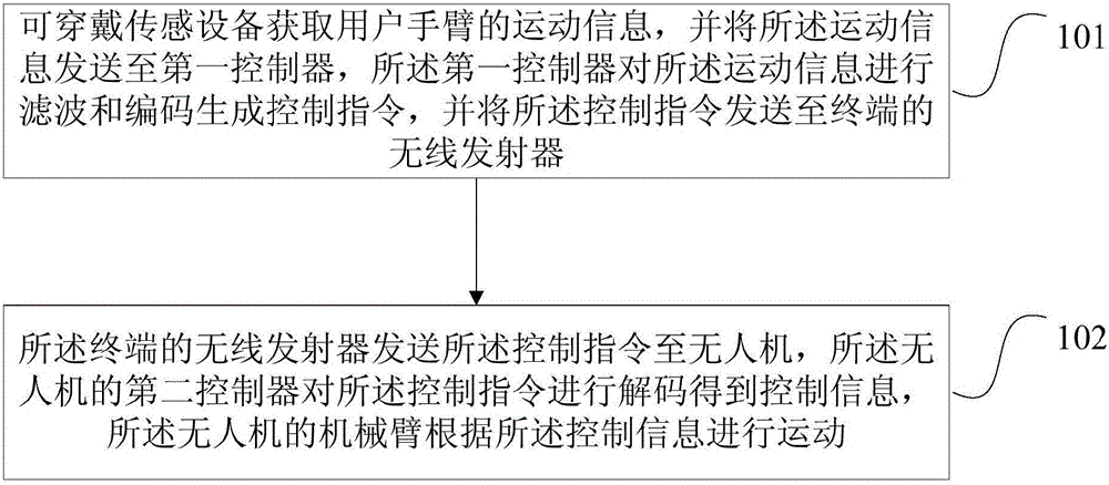
[0025] figure 1 The flow chart of the control method of the UAV mechanical arm provided by Embodiment 1 of the present invention, this embodiment can be applied to the situation that requires high-precision task execution in a complex environment, and the method can be controlled by the UAV and the user equipment to execute, specifically including the following steps:

[0026] Step 101, the wearable sensor device obtains the motion information of the user's arm, and sends the motion information to the first controller, and the first controller filters and encodes the motion information to generate a control command, and sends the motion information The above control command is sent to the wireless transmitter of the terminal.

[0027] Among them, the wearable device can be directly worn on the user's arm, and it can complete powerful interactive functions through integrated hardware and software. Exemplarily, when the user's arm swings, the sensors integrated in the wearable...

Embodiment 2

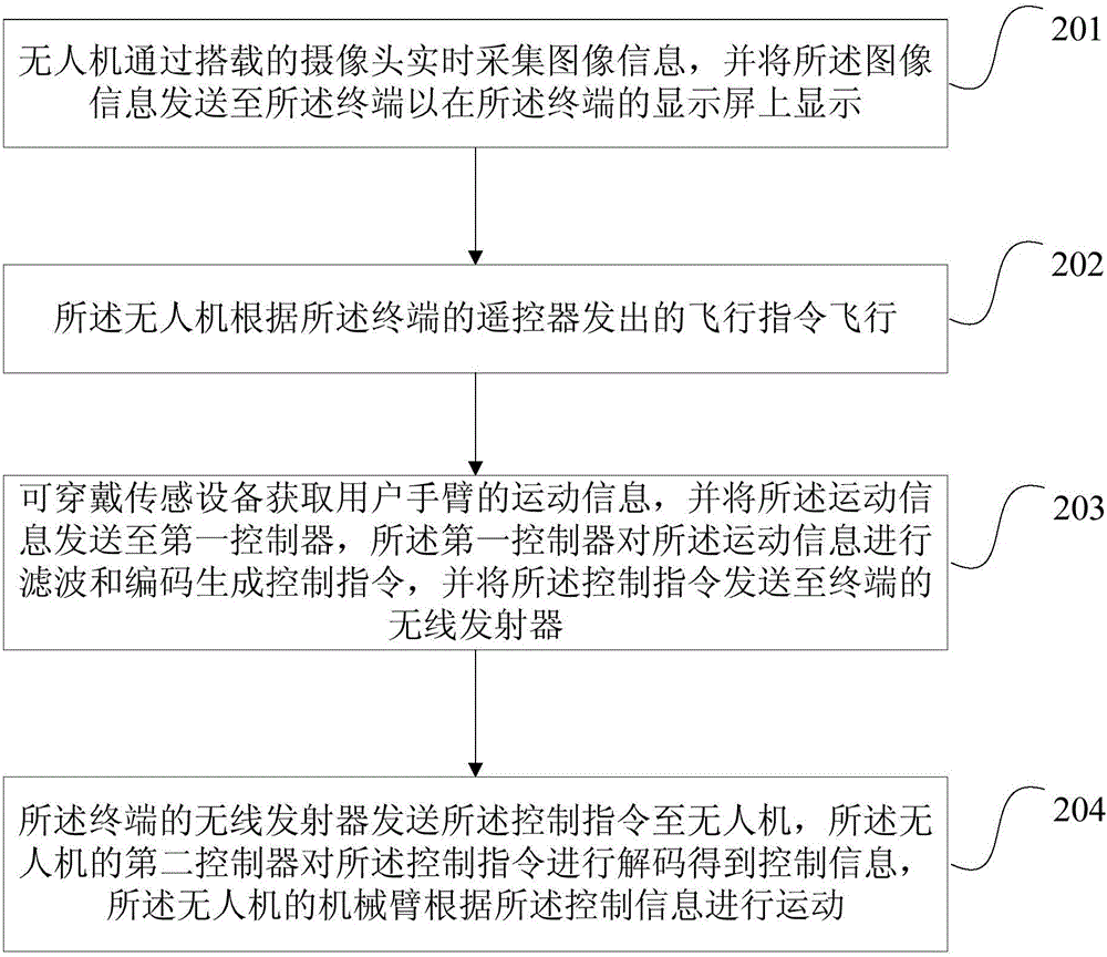
[0033] image 3 It is a flow chart of the control method of the UAV mechanical arm provided by Embodiment 2 of the present invention. On the basis of the above-mentioned embodiments, this embodiment provides a specific process for performing tasks by the UAV. The process consists of It consists of two parts. First, it guides the UAV to fly to the mission location, and then completes the mission execution through the robotic arm, including:

[0034] Step 201, the UAV collects image information in real time through the mounted camera, and sends the image information to the terminal to be displayed on the terminal's display screen.

[0035] Exemplarily, the UAV in this solution uses a multi-rotor UAV. When the UAV is in flight, images are collected in real time and transmitted to the terminal. The terminal displays the surrounding environment of the UAV through the display screen.

[0036] Step 202, the UAV flies according to the flight instruction sent by the remote controller ...

Embodiment 3

[0042] Figure 4 It is a flowchart of the control method of the UAV mechanical arm provided by the third embodiment of the present invention. On the basis of the above-mentioned embodiments, this embodiment provides a specific control process of the mechanical arm. This solution includes the following steps .

[0043]Step 301, the wearable sensor device acquires the motion information of the user's arm, and sends the motion information to the first controller, and the first controller filters and encodes the motion information to generate a control command, and sends the motion information The above control command is sent to the wireless transmitter of the terminal.

[0044] Step 302, the wireless transmitter of the terminal sends the control command to the UAV, the second controller of the UAV decodes the control command to obtain control information, and the robotic arm of the UAV according to The control information is exercised.

[0045] Step 303, the second controller...


PUM


Abstract

The invention discloses a control method and device for a mechanical arm of an unmanned aerial vehicle. The method comprises steps as follows: wearable sensing equipment acquires motion information of an arm of a user and sends the motion information to a first controller, and the first controller filters and encodes the motion information to generate a control command and sends the control command to a wireless emitter of a terminal; and the wireless emitter of the terminal sends the control command to the unmanned aerial vehicle, a second controller of the unmanned aerial vehicle decodes the control command to acquire control information, and the mechanical arm of the unmanned aerial vehicle moves according to the control information. With the scheme, high-precision remote real-time synchronous control on the mechanical arm of the unmanned aerial vehicle is realized, the stability is high, the control method is simple, and complex control actions can be completed, so that the mechanical arm adapts to tasks in complex environments.

Description

technical field [0001] Embodiments of the present invention relate to hardware control technology, and in particular to a control method and device for a robotic arm of a drone. Background technique [0002] With the development of science and technology, people gradually begin to use robots to assist people in their daily work. For some complex tasks, a robot is usually equipped with a mechanical arm to perform more delicate operations. [0003] Existing robots are mostly ground robots, and their robotic arms have certain limitations in the application environment when performing remote tasks. They are generally suitable for land rescue, accident handling, etc., but are not suitable for long-distance high-altitude or water surface tasks. There are also limitations in complex conditions such as a large number of ruins, and the robotic arm of the ground robot. Especially for the water surface environment or the amphibious environment, there are obvious deficiencies in the gr...

Claims


Application Information

Patent Timeline
Patent Type & Authority Applications(China)
IPC IPC(8): B25J9/16B25J13/00
CPCB25J9/1689B25J13/006B64U2101/00G05D1/0094B25J9/162G05B2219/35448B25J9/16
Inventor 郝祁兰功金卜亚圣
Owner SOUTH UNIVERSITY OF SCIENCE AND TECHNOLOGY OF CHINA
Why Eureka
Try Eureka