Rock tension shear test device and method used in tension shear test machine

A testing device and testing machine technology, applied in the direction of testing material strength by applying stable shear force, testing material strength by applying stable tension/compression, measuring devices, etc., can solve the problem of high cost, unguaranteed test accuracy, and control Problems such as the poor effect of the system hydraulic jack on stabilizing the load, etc., achieve the effect of low cost, guaranteed accuracy of test results, and reliable performance

Active Publication Date: 2016-11-02
HEBEI UNIV OF TECH
View PDF5 Cites 18 Cited by
  • Summary
  • Abstract
  • Description
  • Claims
  • Application Information

AI Technical Summary

Problems solved by technology

However, the cost of the first type of test equipment is very expensive. Although the cost of the second type is moderate, the test accuracy cannot be guaranteed due to the lack of control system (for example, the effect of the hydraulic jack to maintain a stable load is not good).

Method used


Image

  • Rock tension shear test device and method used in tension shear test machine
  • Rock tension shear test device and method used in tension shear test machine
  • Rock tension shear test device and method used in tension shear test machine

Examples


Embodiment 1

[0052] A rock tension-shear test device that can be used on a compression-shear tester, see Figure 7 , including 匚-shaped tensile piece Ⅰ1, 匚-shaped tensile piece Ⅱ2, L-shaped guide slide Ⅰ3, L-shaped guide slide Ⅱ4, testing machine loading head Ⅰ91, testing machine loading head Ⅱ92, testing machine loading head Ⅲ93 and testing machine Loading head Ⅳ94

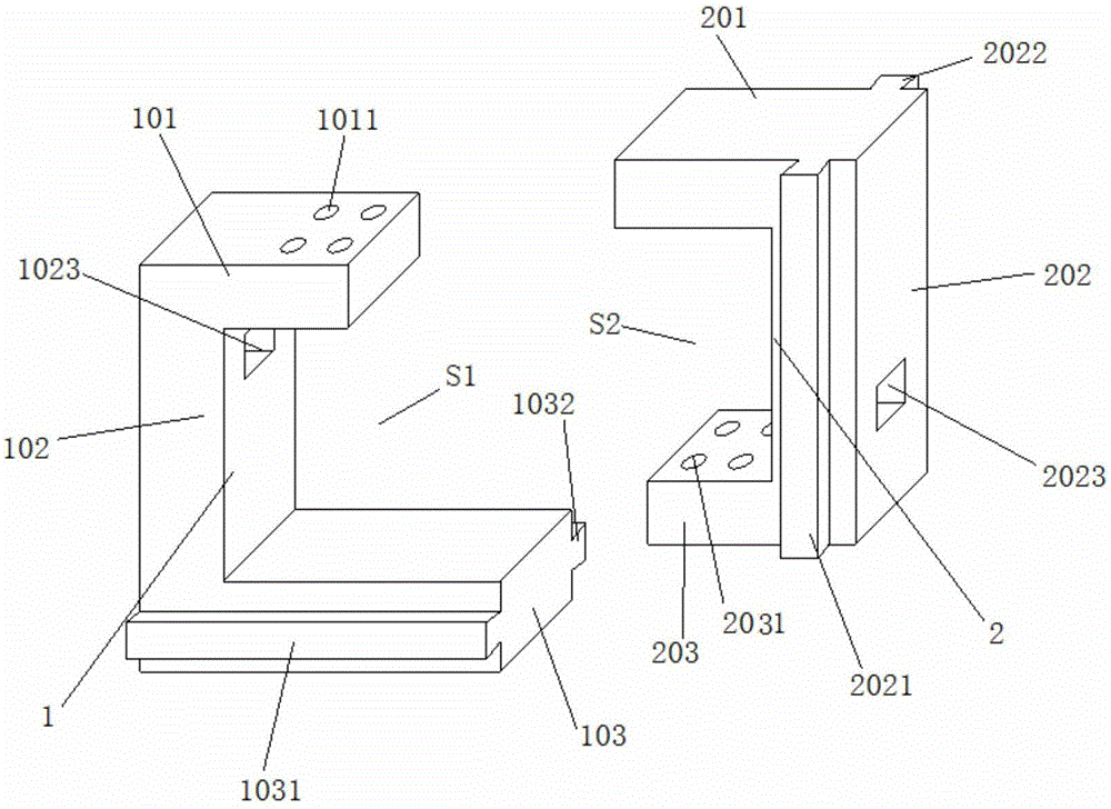
[0053] see figure 1 , the U-shaped tensile member I1 is composed of a top plate I101, a column I102 and a bottom plate I103, and the three enclose and semi-enclose the space IS1. The top plate I101 is shorter than the bottom plate I103.

[0054] The top plate I101 has several threaded holes I1011 running through its upper and lower surfaces.

[0055] The column I102 is provided with a square through hole I1023 running through both sides thereof. An outlet of the square through hole I1023 is in the semi-enclosed space IS1.

[0056] The two sides of the bottom plate I103 have slide rails I-I1031 and slide rails I-II1032 resp...

Embodiment 2

[0073] This embodiment adopts the device of embodiment 1, during the test:

[0074] 1) see Figure 4 , put the rock specimen 8 in the space S.

[0075] In the embodiment, high-strength structural glue can be used to paste the two connecting plates on the upper and lower sides of the rock specimen 8 respectively, and wait for the glue to fully exert its strength (generally at least 24 hours).

[0076] 2) see Figure 7 , apply a predetermined normal force to the rock specimen 8 through the loading head I91 of the testing machine. That is, the loading head I91 of the testing machine is pressed to the U-shaped tensile member II2, and the rock specimen 8 is stretched up and down by the connection blocks 6 / 60 bonded to its upper and lower ends respectively.

[0077] It is worth noting that the bottom of the U-shaped tensile member II2 is suspended, and when the loading head I91 of the testing machine applies a downward force, if the rock breaks, the U-shaped tensile member II2 wi...


PUM


Abstract

The present invention aims at the lack of rock tension shear test equipment and provides a rock tension shear test device and method used in tension shear test machine. The device comprises a rightwards inverted U-shaped drawing part I, a rightwards inverted U-shaped drawing part II, an L-shaped guide slider I, an L-shaped guide slider II, a test machine loading head I, a test machine loading head II, a test machine loading head III and a test machine loading head IV. The rightwards inverted U-shaped drawing part I and the rightwards inverted U-shaped drawing part II enclose into an S-shaped area. A rock specimen is placed in the space S. The test machine loading head I applies predetermined normal force to the rock specimen; and test machine loading head II applies shearing force to the rock specimen. The load progress of is paid close attention to, once the rock specimen is damaged, a normal loading system is immediately shut down, and then a shear loading system is shut down to complete the test. The invention provides convenient, inexpensive and accurate test means for obtaining the mechanical characteristics of rock under the combined load of tension and shear.

Description

technical field [0001] The invention relates to a tensile-shear combined mechanical test of materials such as rocks. Background technique [0002] Tension-shear failure of rock is a common failure mode in rock mass engineering. For example, the excavation of deep caverns unloads the normal ground stress of the side wall and concentrates the tangential ground stress. When the unloading is very strong, tensile shear failure may occur. Another example is that the excavation and unloading of a rocky slope can lead to a tensile stress area on the upper slope, and the rock mass in this area is generally in a combined tension-shear stress state that is both tensioned and sheared. Another example is the landslides and earthquake landslides under the action of a large amount of self-weight, which show that the rear edge of the slope often suffers from tensile damage. Therefore, it is of great significance to study the mechanical properties of rock in tension and shear for the desig...

Claims


Application Information

Patent Timeline
Patent Type & Authority Applications(China)
IPC IPC(8): G01N3/08G01N3/24
CPCG01N3/08G01N3/24G01N2203/0017G01N2203/0025
Inventor 黄达岑夺丰
Owner HEBEI UNIV OF TECH
Why Eureka
Try Eureka