
A PSS negative damping detection method

A detection method and negative damping technology, applied in the direction of measuring electricity, measuring devices, measuring electrical variables, etc., can solve problems such as lack of strict theoretical basis

Active Publication Date: 2018-07-03
SICHUAN UNIVERSITY OF SCIENCE AND ENGINEERING
View PDF5 Cites 0 Cited by
  • Summary
  • Abstract
  • Description
  • Claims
  • Application Information

AI Technical Summary

Problems solved by technology

[0007] The limitation of this method is: in a certain oscillation mode, judging whether the PSS damping is positive or negative needs to compare the oscillation waveforms when PSS is put in and out.
[0009] The limitation of this method is that the similarity comparison method used to detect the PSS negative damping of a certain generator lacks strict theoretical basis

Method used


Image

  • A PSS negative damping detection method
  • A PSS negative damping detection method
  • A PSS negative damping detection method

Examples


specific Embodiment 1

[0120] The PSS negative damping detection method shown (as Figure 8 shown), the specific detection method steps are:

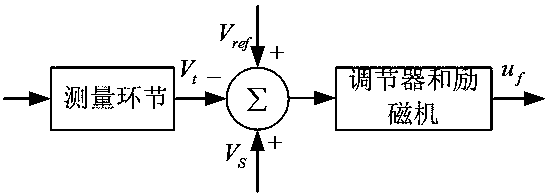
[0121] Step 1. Obtain the excitation voltage u of the generator under the rated working condition of the generator fN and excitation current i fN , and calculate the field winding resistance Obtain the excitation voltage u during generator oscillation f , excitation current i f , Generator terminal voltage V t and the additional excitation reference voltage V of the PSS output S ;

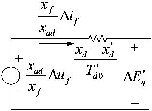
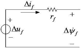
[0122] Step 2. Calculating the Flux Linkage Differential During Generator Oscillation

[0123] Step three, for u f i f , V t , V S , Perform identification to obtain the excitation voltage amplitude Δu in the main mode fm, attenuation factor σ uf , frequency f uf , the initial phase α; obtain the excitation current amplitude Δi in the main mode fm , attenuation factor σ if , frequency f if , the initial phase β; obtain the terminal voltage amplitude ΔV in the...

specific Embodiment 2

[0158] On the basis of specific embodiment 1, the method steps also include calculating the oscillation energy, and when the PSS is put into operation, the excitation system injects the oscillation energy When PSS exits, the estimated field current is Set the excitation system to inject oscillation energy when PSS exits Compare U ex and U ex0 size, if U ex ex0 Then PSS produces positive damping; if U ex > U ex0 Then PSS produces negative damping.

[0159] In this specific example, u ex =-0.0739, U ex0 =1.7478

specific Embodiment 3

[0160] The difference with specific embodiments 1 and 2 is that the drawing method is not used for judgment, but the comparison between the excitation system injection oscillation energy when PSS is put in and the excitation system injection oscillation energy when PSS exits is used to accurately and detailedly determine the occurrence of PSS. Whether it is positive damping or negative damping, so as to detect the PSS negative damping.


PUM


Abstract

The invention provides a PSS (power system stabilizer) negative damping detection method. According to the PSS negative damping detection method, intuitive judgment of PSS positive and negative damping can be realized according to a graphical method on the basis of vector analysis, so as to realize detection of the PSS negative damping, or whether damping generated by a PSS is positive damping or negative damping can be judged more accurately and minutely by further comparing oscillation energy injected by an excitation system when the PSS is powered on with oscillation energy injected by the excitation system when the PSS is powered off, so as to detect the PSS negative damping for detection of the PSS negative damping, or whether damping generated by the PSS is positive damping or negative damping can be judged accurately and minutely by directly comparing the oscillation energy injected by the excitation system when the PSS is powered on with the oscillation energy injected by the excitation system when the PSS is powered off. The PSS negative damping detection method can be used for detecting whether the PSS of a generator generates negative damping for a certain oscillation mode or not, and switching of working conditions is not needed during detection.

Description

technical field [0001] The invention relates to a PSS negative damping detection method, in particular to a PSS negative damping detection method applicable to the technical field of power system stability control. Background technique [0002] Low frequency oscillation is one of the major problems threatening modern power systems. When low-frequency oscillation occurs, the voltage, power, and frequency in the system will all oscillate, which will seriously affect the operation of the system. Power System Stabilizer (PSS) is the most widely used low-frequency oscillation suppression device. By feeding back the generator speed, frequency, electromagnetic power and other signals, after filtering, amplification, phase compensation and other processing, an additional excitation reference signal is generated to act on the excitation device to change the excitation voltage and then change the electromagnetic power of the generator, so that in the generator rotor A positive dampi...

Claims


Application Information

Patent Timeline
Patent Type & Authority Patents(China)
IPC IPC(8): G01R31/00G01R31/34
CPCG01R31/00G01R31/34G01R31/343G01R31/346
Inventor 杨毅强吴浩李兆飞
Owner SICHUAN UNIVERSITY OF SCIENCE AND ENGINEERING
Learn More