
Microgrid inverter carrier wave phase-shifting synchronization system and carrier wave phase-shifting synchronization method

A carrier phase-shifting and synchronous system technology, applied in the field of micro-grid, can solve problems such as unfavorable system modular management, unfavorable micro-grid inverter free switching, etc., to reduce AC current harmonics, improve reliability and accuracy performance, the effect of suppressing parallel resonance

Pending Publication Date: 2016-11-02
EAST GRP CO LTD
View PDF3 Cites 16 Cited by
  • Summary
  • Abstract
  • Description
  • Claims
  • Application Information

AI Technical Summary

Problems solved by technology

When the existing technology solves single-point failure or redundant control, the system needs to suspend work for maintenance, which is not conducive to the free switching of micro-grid inverters, and is not conducive to system modular management

Method used


Image

  • Microgrid inverter carrier wave phase-shifting synchronization system and carrier wave phase-shifting synchronization method
  • Microgrid inverter carrier wave phase-shifting synchronization system and carrier wave phase-shifting synchronization method
  • Microgrid inverter carrier wave phase-shifting synchronization system and carrier wave phase-shifting synchronization method

Examples


Embodiment Construction

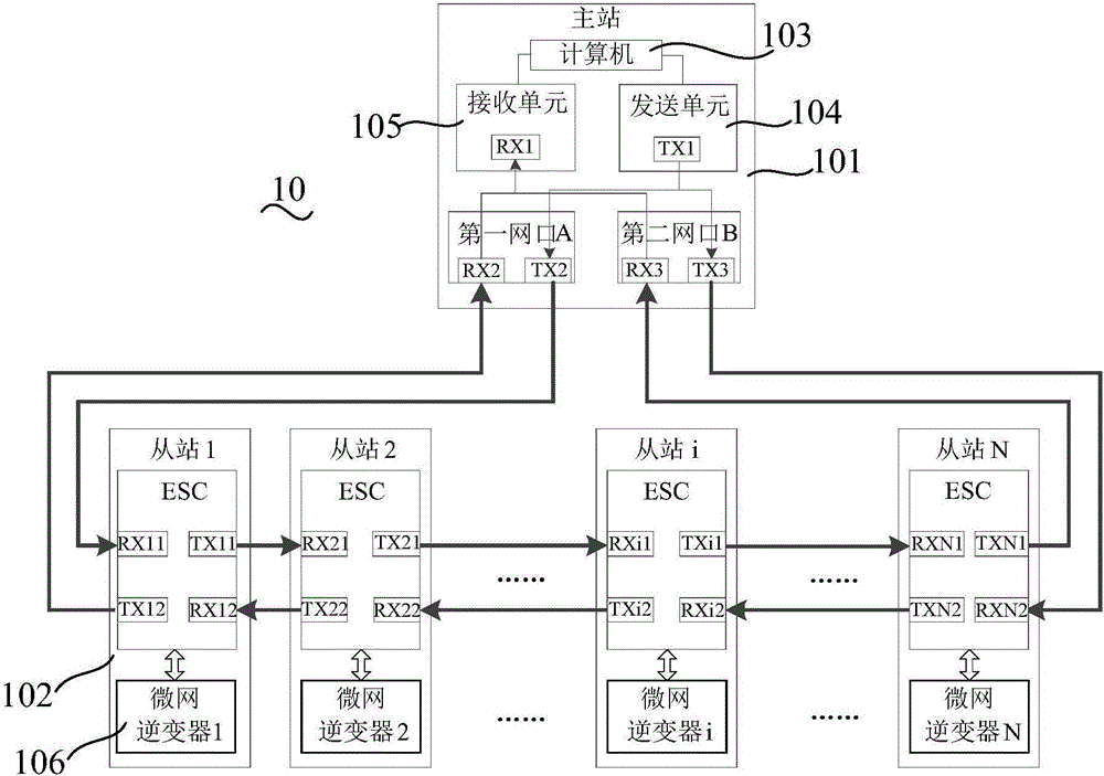
[0038] In order to make the above objects, features and advantages of the present invention more comprehensible, specific implementations of the present invention will be described in detail below in conjunction with the accompanying drawings. In the following description, numerous specific details are set forth in order to provide a thorough understanding of the present invention. However, the present invention can be implemented in many other ways different from those described here, and those skilled in the art can make similar improvements without departing from the connotation of the present invention, so the present invention is not limited by the specific embodiments disclosed below.

[0039] see figure 1 , which is a schematic structural diagram of a microgrid inverter carrier phase-shift synchronization system 10 in an embodiment. A microgrid inverter carrier phase-shift synchronization system 10 includes a master station 101 and several slave stations 102 . The mast...


PUM


Abstract

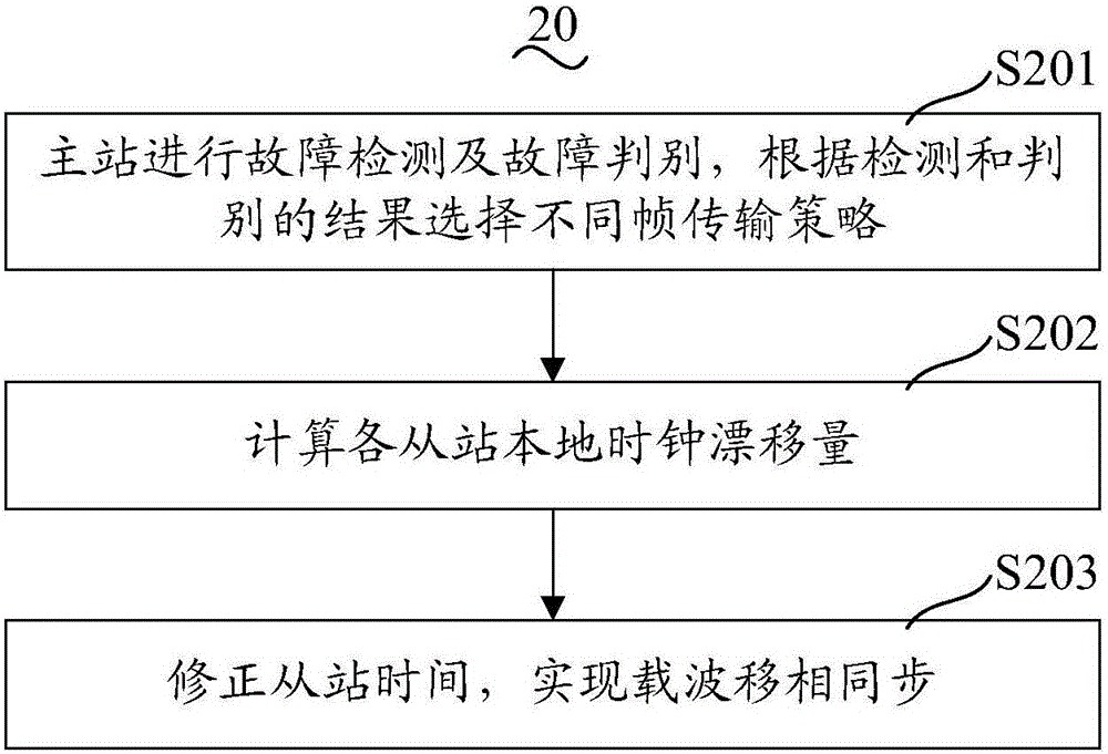
A microgrid inverter carrier wave phase-shifting synchronization system comprises a master station and a number of slave stations. The master station comprises a first network port, a second network port, a computer, a sending unit and a receiving unit. The slave station comprises a number of microgrids and control chips, and each control chip is correspondingly connected to a microgrid inverter. A carrier wave phase shifting synchronization method comprises the following steps: in a first step, the master station carries out fault detection operation and fault discrimination operation and selects different frame transmission strategies according to results of the detection operation and the discrimination operation; in a second step, local clock drift distance of each slave station is calculated; in a third step, time of the slave stations is corrected, and carrier wave phase-shifting synchronization is achieved. Via the microgrid inverter carrier wave phase-shifting synchronization system and the carrier wave phase-shifting synchronization method, reliability and accuracy of the carrier wave phase-shifting synchronization of the micro-network inverter parallel system can be improved, alternating current harmonics can be reduced after all the inverters are connected in parallel, and parallel resonance can be suppressed.

Description

technical field [0001] The invention relates to the technical field of microgrids, in particular to a microgrid inverter carrier phase-shift synchronization system and a carrier phase-shift synchronization method. Background technique [0002] In the parallel system of microgrid inverters, parallel resonance is a key issue affecting the reliable and stable operation of microgrid. The parallel operation of micro-grid inverters with independent DC source input to the common AC bus is prone to resonance problems. Resonance will seriously distort the grid-connected current, increase losses, and reduce system efficiency. Inconsistency factors such as modulation wave and carrier wave of each inverter module can easily cause current resonance among inverter modules. Generally, LCL filter parameter optimization and the introduction of virtual impedance are used to suppress the resonance problem caused by parallel inverters. These methods have a certain suppression effect on current...

Claims


Application Information

Patent Timeline
Patent Type & Authority Applications(China)
IPC IPC(8): H04L7/04H04L12/437H04J3/06
CPCH04J3/0658H04J3/0682H04L7/041H04L12/437
Inventor 曹元峥汪海宁张涛张晓安苏建徽徐海波
Owner EAST GRP CO LTD
Learn More