Sunroof structure for vehicle

A vehicle and sunroof technology, applied in the field of vehicle sunroof structure, can solve problems such as obstruction

Active Publication Date: 2016-11-02
HONDA MOTOR CO LTD
View PDF5 Cites 2 Cited by
  • Summary
  • Abstract
  • Description
  • Claims
  • Application Information

AI Technical Summary

Problems solved by technology

Therefore, the shape of the lower half of the rubber member is restricted by the guide groove, which hinders the improvement of the degree of freedom in design.

Method used


Image

  • Sunroof structure for vehicle
  • Sunroof structure for vehicle
  • Sunroof structure for vehicle

Examples


Embodiment

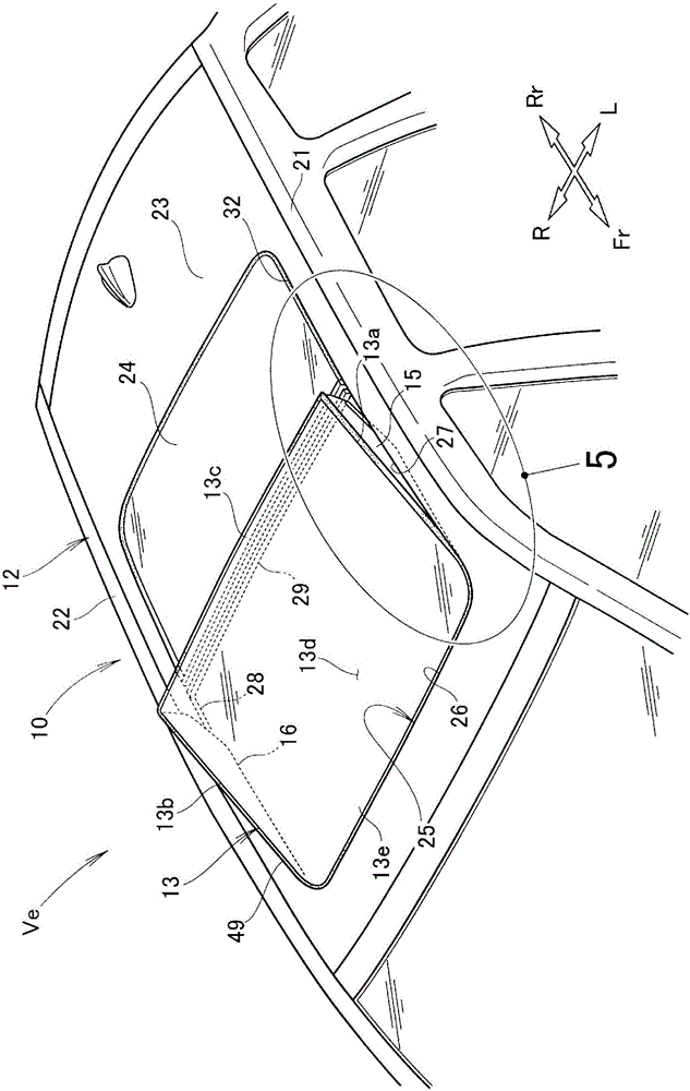
[0069] The sunroof structure 10 of the vehicle according to the embodiment will be described.

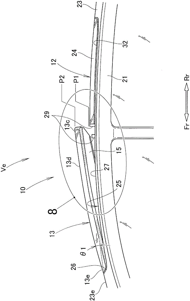
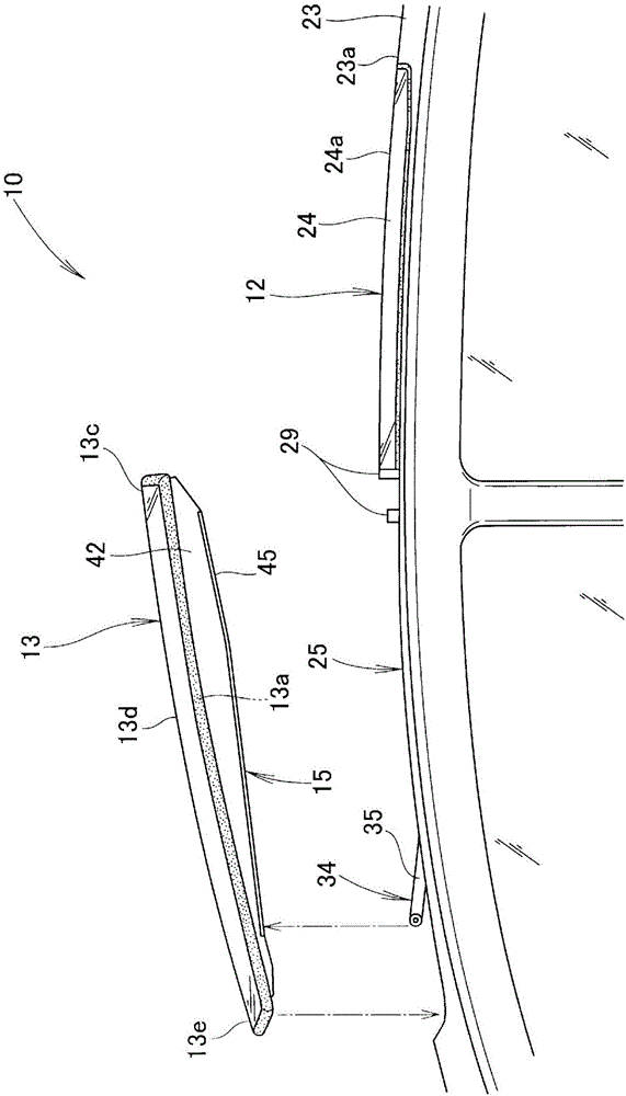
[0070] Such as figure 1 , figure 2 As shown, the sunroof structure 10 of the vehicle includes: a roof (fixed roof) 12, which forms the top of the vehicle Ve; a movable roof 13, which is provided on the roof 12; and a left lip 15, which is provided on the movable roof 13 The left side (the side in the vehicle width direction) 13a; and the right lip 16, which is provided on the right side (the side in the vehicle width direction) 13b of the movable roof 13.

[0071] The left lip 15 and the right lip 16 are symmetrical members, and the left lip 15 will be described below, and the description of the right lip 16 will be omitted.

[0072] The roof 12 includes: the left side roof rail 21, which forms the left side of the roof; the right side roof rail 22, which forms the right side of the roof; and the roof body 23, which is provided on the left side roof side Between the beam 21 and the right...


PUM


Abstract

A sunroof structure (10) for a vehicle is provided with a stationary roof (12) for forming the top part of the vehicle (Ve); a movable roof (13) for opening and closing a front opening (25) provided in the stationary roof (12); and a left side lip (15) provided to the left side section (13a) of the movable roof (13). The left side lip (15) is provided so as to be located at a distance from the stationary roof (12) when the movable roof (13) is in a tilt-up position. The left side lip (15) is provided with: a lip body (42) protruding downward from the left side section (13a) of the movable roof (13); and a protrusion (45) protruding from the lower end (42a) of the lip body (42) toward the outside in the width direction of the vehicle.

Description

Technical field [0001] The present invention relates to a sunroof structure of a vehicle, which is configured such that an opening is provided on the roof of the vehicle, a movable roof is supported by the opening, and the opening can be opened and closed by the movable roof. Background technique [0002] As the sunroof structure of a vehicle, the following structure is known: the roof of the vehicle is formed by a roof (fixed roof), an opening is formed in the roof, and the movable roof (cover) is supported in the opening so as to be opened and closed. Windshields are provided on both sides of the roof in the vehicle width direction. [0003] The windshield is provided in a state in contact with both sides of the opening (that is, the roof). Therefore, in a state where the movable roof is opened, the space between the both sides of the opening and the movable roof is kept in a sealed state by the windshield (for example, refer to Patent Document 1). [0004] However, the sunroof o...

Claims


Application Information

Patent Timeline
Patent Type & Authority Applications(China)
IPC IPC(8): B60J7/05B60J7/22
CPCB60J7/0046B60J7/1642B60J7/11B60J7/22
Inventor 栗田诚佐藤芳和
Owner HONDA MOTOR CO LTD
Why Eureka
Try Eureka