
Medical full-automatic stable lifting type mobile pushing bed

A fully automatic, lifting technology, which is applied in the field of medical push beds, can solve the problems of unstable lifting, low degree of automation, and insufficient functions, so as to improve the diversity of functions, improve the degree of intelligence, and improve work efficiency. Effect

Inactive Publication Date: 2016-11-09
颜秋羊
View PDF10 Cites 0 Cited by
  • Summary
  • Abstract
  • Description
  • Claims
  • Application Information

AI Technical Summary

Problems solved by technology

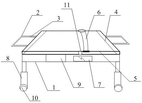
[0003] In order to solve the above-mentioned technical problems, the present invention provides a fully automatic and stable lifting mobile push bed for medical use, so as to solve the problems of the existing medical push bed such as insufficient functions, inconvenient use, unstable lifting and low operating effect. , complex operation, low practical efficiency, time-consuming and laborious, low degree of automation, high maintenance cost, and it is not a problem of a fully automatic and stable lifting mobile push bed. A fully automatic stable lifting mobile push bed for medical use, including a bed frame , lifting handle, handle cover, chute, sliding bed board, fixed strap, motor, telescopic rod, fully automatic control device, moving wheel and folding shaft, and the described bed frame is connected and arranged at the bottom of the sliding bed board through the chute; The handle sleeve is set on the outside of the handle; the folding shaft is connected to the folding part of the sliding bed; the fully automatic control device is electrically connected to the left side of the motor; the moving wheel is connected to the At the bottom of the telescopic rod; the fixed strap is connected and fixed on the upper part of the sliding bed board

Method used


Image

  • Medical full-automatic stable lifting type mobile pushing bed
  • Medical full-automatic stable lifting type mobile pushing bed

Examples


Embodiment

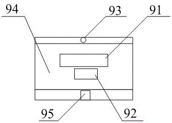
[0017] Such as figure 1 , attached figure 2 As shown, the present invention provides a fully automatic and stable lifting mobile push bed for medical use, including a bed frame 1, a lifting handle 2, a handle cover 3, a chute 4, a sliding bed board 5, a fixed strap 6, a motor 7, a telescopic Rod 8, automatic control device 9, moving wheel 10 and folding shaft 11, the bed frame 1 is connected and arranged on the bottom of the sliding bed board 5 through the chute 4; the handle cover 3 is set on the outside of the lifting handle 2 The folding shaft 11 is connected to the folding part of the sliding bed board 5; the fully automatic control device 9 is electrically connected to the left side of the motor 7; the moving wheel 10 is connected to the telescopic rod 8 Bottom; the fixed strap 6 is connected and fixed on the upper part of the sliding bed board 5 .

[0018] Described fully automatic control device 9 comprises controller 91, sensor 92, indicator lamp 93, control panel 9...


PUM


Abstract

The invention provides a medical full-automatic stable lifting and dropping type mobile pushing bed. The medical full-automatic stable lifting and dropping type mobile pushing bed comprises a bed frame, lifting handles, handle sleeves, a sliding groove, a sliding bed board, a fixing binding belt, an electromotor, telescopic rods, a full-automatic control device, mobile wheels and a folding shaft. The bed frame is arranged at the bottom of the sliding bed board in a connected mode through the sliding groove. The lifting handles are sleeved with the handle sleeves. The folding shaft is connected with a folding part arranged on the sliding bed board. According to the full-automatic control device, through the arrangement of the sliding groove, the telescopic rods, the folding shaft and the mobile wheels, cooperation with sliding of the bed board is promoted, the stable lifting and dropping effect is achieved, flexibility and practicality are achieved, and telescopic motion is convenient; in cooperation with the needed lifting and dropping height, the optimal practical effect is achieved, time and labor are further saved, the intelligence degree is increased, movement is flexible, working efficiency is improved, functional diversity is perfected accordingly, and the full-automatic effect is achieved.

Description

technical field [0001] The invention belongs to the technical field of medical pushers, and in particular relates to a fully automatic and stable lifting type mobile pusher for medical use. Background technique [0002] At present, medical beds refer to appliances or other articles used on the human body. Their functions on the surface of the human body are not obtained by means of pharmacology, immunology or metabolism, but these means may participate and play a certain auxiliary role; The purpose of use is to achieve the following intended purposes: (1) prevention, diagnosis, treatment, monitoring, and mitigation of diseases; (2) diagnosis, treatment, monitoring, mitigation, and compensation of injuries or disabilities. The function of the bed is not perfect, it is inconvenient to use, it is not stable to lift, the effect is poor, the operation is complicated, the practical efficiency is low, time-consuming and laborious, the degree of automation is low, and the maintenanc...

Claims


Application Information

Patent Timeline
Patent Type & Authority Applications(China)
IPC IPC(8): A61G1/02A61G1/04A61G7/10
CPCA61G1/02A61G1/04A61G7/1026
Inventor 颜秋羊
Owner 颜秋羊
Learn More