Decanting-type waste muddy water recycling pool

A recovery tank and sludge water technology, which is applied in the direction of settling tank, sedimentation regulating device, feeding/discharging device of settling tank, etc., can solve the problems of large fluctuations in water quality of recycled water, poor water separation effect, and poor secondary utilization effect and other problems, to achieve the effect of low engineering cost and operating cost, simple structure and low maintenance cost

Inactive Publication Date: 2016-11-09
YELLOW RIVER ENG CONSULTING
View PDF5 Cites 5 Cited by
  • Summary
  • Abstract
  • Description
  • Claims
  • Application Information

AI Technical Summary

Benefits of technology

This new design for recycling wastewater treatment systems uses specialized tanks that collect large amounts of liquid from various sources like septic fields or industrial processes. These tanks have several technical advantages over existing designs: they can be easily installed without requiring expensive repairs; it saves money on maintainability costs while still being effective because there's no residue left behind after each usage period (which makes them more efficient). Additionally, these tanks provide consistently good results with minimal environmental impact due to their small size compared to traditional methods.

Problems solved by technology

The technical problem addressed by this patented technology relates to improving the efficiency at treating domestic wastewater that has been treated with various methods such as chemical precipitation or biological processes. This can lead to poor performance due to changes made during these procedures affecting the properties of the recovered liquid (sludges) produced from it.

Method used


Image

  • Decanting-type waste muddy water recycling pool
  • Decanting-type waste muddy water recycling pool
  • Decanting-type waste muddy water recycling pool

Examples


Embodiment Construction

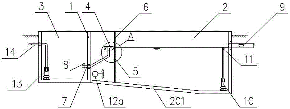
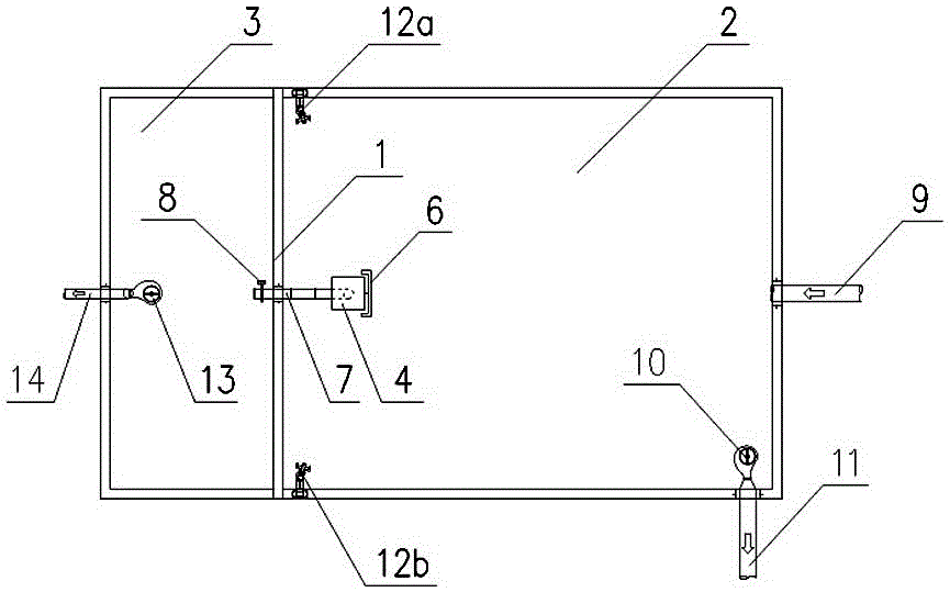
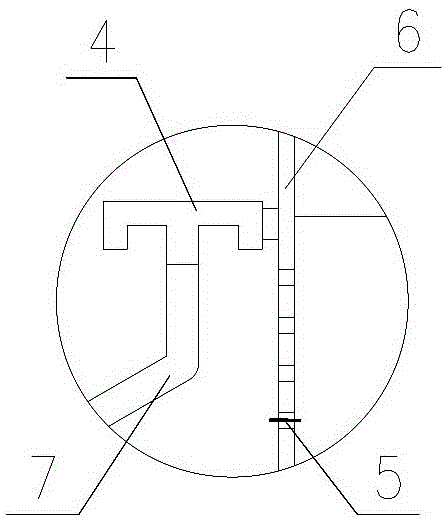
[0010] Such as Figure 1-3 As shown, the decanting waste sludge water recovery tank of the present invention comprises a steel concrete structure recovery tank body, in which a partition wall 1 is arranged, and the partition wall 1 divides the recovery tank body into a sedimentation area 2 and a water collection area 3. The bottom wall 201 of the sedimentation zone 2 is arranged gradually downward along the partition wall 1 toward the opposite pool wall, which is beneficial for the sedimentation to flow to the sludge outlet pipe 11 along the inclined direction of the bottom wall 201 . A buoy type decanter 4 and a movable insert limit pin 5 are installed near the partition wall 1 in the sedimentation area 2 (such as image 3 Shown) the vertical guide rail 6, the buoy of the buoy type water decanter 4 is slidably connected with the vertical guide rail 6, and the water outlet of the buoy type water decanter 4 is connected with the water guide pipe 7. The above-mentioned vertica...


PUM


Abstract

The invention discloses a decanting-type waste muddy water recycling pool. The decanting-type waste muddy water recycling pool comprises a recycling pool body, wherein the recycling pool body is divided by a partition wall into a mud settling zone and a water collecting zone, the bottom wall of the mud settling zone gradually inclines towards the opposite side wall along the partition wall, a buoy-type decanting device and a vertical guide rail are arranged in the mud settling zone, the buoy-type decanting device is connected with the vertical guide rail in a sliding manner, a water outlet of the buoy-type decanting device is connected with a water guide pipe, and the water guide pipe is arranged in the partition wall in a sealing manner and extends to the water collecting zone; a muddy water inlet pipe is arranged in the mud settling zone, the side wall of the mud settling zone is provided with a sludge outlet pipe communicated with a sludge pump, and two side walls of the mud settling zone are respectively fixedly provided with a submarine-type sludge stirrer; and a secondary water outlet pipe communicated with a recycling water pump is arranged in the water collecting zone. The decanting-type waste muddy water recycling pool is simple in structure, relatively stable in water quality and water quantity of the recycled secondary water and relatively low in engineering cost and operation cost of equipment.

Description


Claims


Application Information

Patent Timeline
Owner YELLOW RIVER ENG CONSULTING
Why Eureka
Try Eureka