Biomass ash-based semidry process desulfurization and denitrification system and method

A semi-dry desulfurization and biomass ash technology, applied in the field of flue gas pollution control, can solve the problems of ineffective utilization of biomass ash and energy waste, reduce the generation of wastewater and solid waste, reduce disproportionation reactions, and apply promising effect

Inactive Publication Date: 2016-11-09
SHANDONG UNIV +2
View PDF5 Cites 6 Cited by
  • Summary
  • Abstract
  • Description
  • Claims
  • Application Information

AI Technical Summary

Problems solved by technology

However, in the existing flue gas desulfurization and denitrification methods, because the flue gas is firstly subjected to dust removal treatment, and the biomass ash generated by biomass combus...

Method used


Image

  • Biomass ash-based semidry process desulfurization and denitrification system and method
  • Biomass ash-based semidry process desulfurization and denitrification system and method

Examples


Embodiment 1

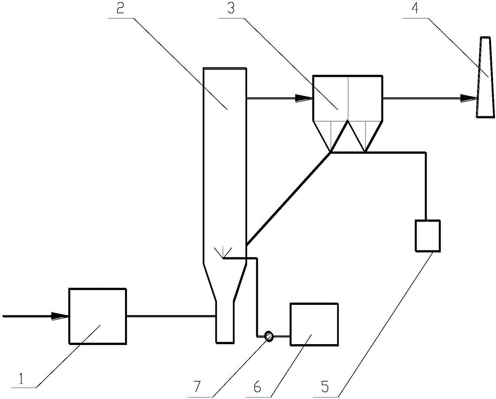
[0042] Such as figure 1 As shown, a semi-dry desulfurization and denitrification system based on biomass ash includes an oxidation device 1, a semi-dry purification tower 2, a dust collector 3, and a chimney 4. The oxidation device 1 communicates with the semi-dry purifier 2 for Provide oxides that oxidize nitrogen oxides, the semi-dry purification tower 2 is connected with the flue gas source, and is used for semi-dry desulfurization and denitrification of the flue gas, and the dust collector 3 is located downstream of the semi-dry purifier 2, It is used to remove dust from the flue gas after desulfurization and denitrification. The chimney 4 is located downstream of the dust collector 3 and is used to discharge the purified flue gas.

[0043]The oxidation device 1 is located between the semi-dry purifier 2 and the flue gas source. After the nitric oxide in the flue gas is oxidized, it enters the semi-dry purifier 2 for desulfurization and denitration reactions.

[0044] The...

Embodiment 2

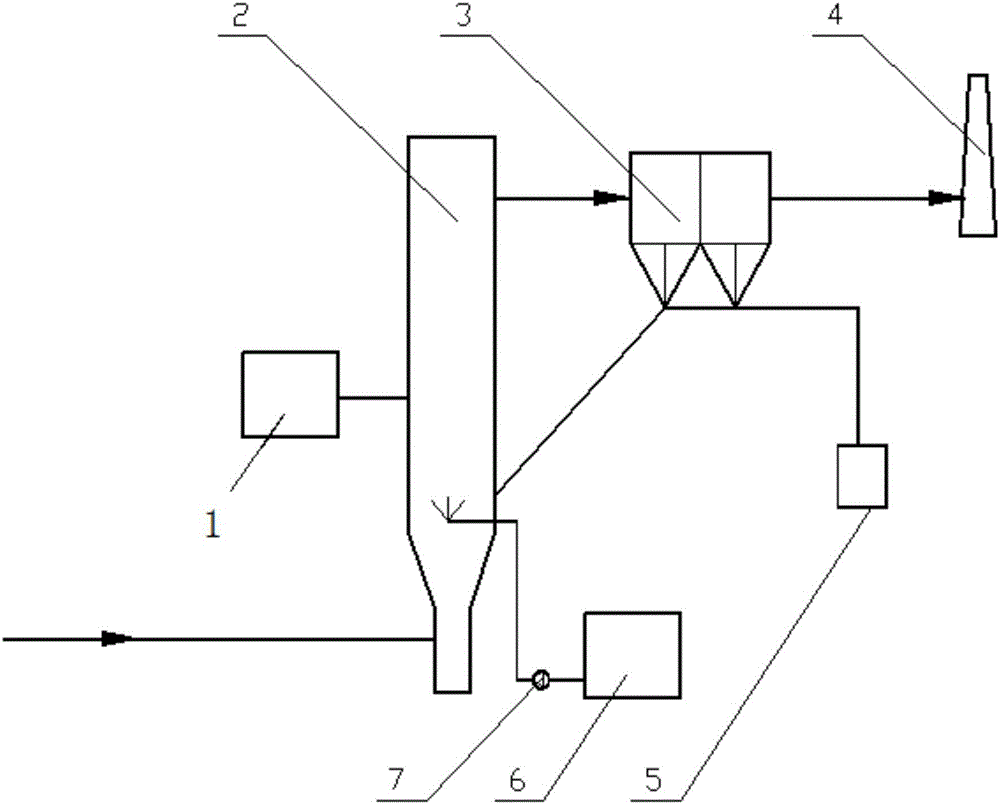
[0060] Such as figure 2 As shown, the semi-dry purifier 2 is directly connected to the flue gas source, the oxidation device 1 is connected to the interior of the semi-dry purifier 2, and the oxidation device 1 directly puts the oxidant into the semi-dry purifier 2 for oxidation reaction.

[0061] The oxidation device 1 may be an ozone generator.

[0062] A semi-dry desulfurization and denitrification method based on biomass ash, comprising the steps of:

[0063] The flue gas from the flue gas source first enters the semi-dry purifier 2, and ozone is passed into the semi-dry purifier 2 to adjust the temperature and humidity of the flue gas in the semi-dry purifier 2, and perform desulfurization and denitrification reactions The flue gas after desulfurization and denitrification flows out from the upper outlet of the semi-dry purifier 2, and is discharged after dust removal.

[0064] Adjust the temperature of the flue gas in the semi-dry purifier 2 to be 160° C., and the moi...


PUM


Abstract

The invention discloses a biomass ash-based semidry process desulfurization and denitrification system and method. The biomass ash-based semidry process desulfurization and denitrification system comprises an oxidation device, a semidry process purification tower, a dust collector and a chimney, wherein both the oxidation device and a biomass conbustion fume source are communicated with a semidry process purifier; nitrogen dioxide generated after nitric oxide in fume is oxidized by an oxidant in the oxidation device, and sulfur dioxide in the fume, are absorbed by the biomass ash in the fume, and then desulfurization and denitrification of the fume are achieved; the dust collector is positioned at the downstream of the semidry process purifier and is used for separating and removing the biomass ash in the fume; the chimney is positioned at the downstream of the dust collector and is used for discharging the fume after the dust is removed. Compared with the conventional desulfurization and denitrification technique, the biomass ash-based semidry process desulfurization and denitrification system is free of oxidant or massive spraying alkaline water, and has the advantages of being high in removal efficiency, free of secondary pollution and other resource consumption, and the like.

Description

technical field [0001] The invention belongs to the field of flue gas pollution control, in particular to a semi-dry desulfurization and denitrification system and method based on biomass ash. Background technique [0002] Biomass is an indispensable part of my country's energy structure. Biomass direct combustion power generation is an important way for large-scale utilization of biomass energy. It has attracted everyone's attention due to its advantages such as good power quality, high reliability, and less pollution. The pollutants produced by biomass combustion are mainly SO 2 , NOx and dust, but due to the low content of sulfur and nitrogen in biomass raw materials, SO in the flue gas 2 and NOx content is generally 100-250mg / Nm 3 . Traditional biomass power plants generally only install dust removal devices, and do not need to consider SO 2 and NOx control. my country's "Emission Standards of Air Pollutants for Thermal Power Plants GB-13223-2011" stipulates the sm...

Claims


Application Information

Patent Timeline
IPC IPC(8): B01D53/80B01D53/60B01D53/75B01D53/56
CPCB01D53/56B01D53/60B01D53/75B01D53/80Y02A50/20
Inventor 张立强马春元王鹏崔琳赵传宁
Owner SHANDONG UNIV
Why Eureka
Try Eureka