Electron beam-oxygen synergistic desulfurization and denitrification system and method

A desulfurization and denitration, electron beam technology, applied in the field of flue gas treatment, can solve the problems of limited effect of electron beam irradiation, limited mixing range of ammonia gas and flue gas, and difficulty in achieving the mixing effect of flue gas and ammonia gas. Adverse effects, effects of improving service life

Pending Publication Date: 2020-07-03
GUANGDONG J TECH ENVIRONMENT SCI CO LTD
View PDF3 Cites 2 Cited by
  • Summary
  • Abstract
  • Description
  • Claims
  • Application Information

AI Technical Summary

Problems solved by technology

However, the mixing range of ammonia and flue gas in the electron beam ammonia desulfurization and denitrification reactor is limited, and it is difficult to achieve an ideal mixing effect between flue gas and ammonia, and the effect of electron beam irradiation is limited.

Method used


Image

  • Electron beam-oxygen synergistic desulfurization and denitrification system and method
  • Electron beam-oxygen synergistic desulfurization and denitrification system and method
  • Electron beam-oxygen synergistic desulfurization and denitrification system and method

Examples


Embodiment 1

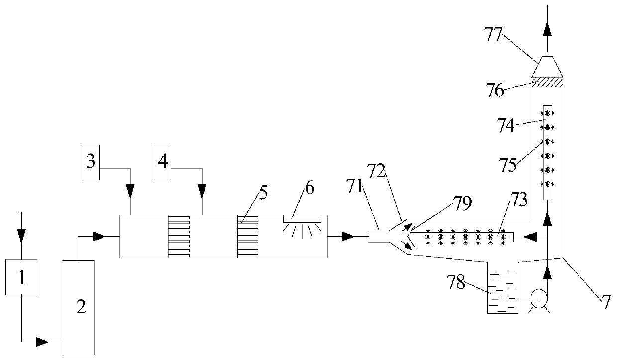
[0072] This embodiment provides an electron beam and oxygen synergistic desulfurization and denitrification system. The electron beam and oxygen synergistic desulfurization and denitrification system includes a dust removal device 1, a spray device 2, a mixing reaction device, an absorption device 7, an oxygen supply device 4, and ammonia Air supply device 3.

[0073] The dust removal device 1 is a cyclone separator, and the spray device 2 is a spray tower.

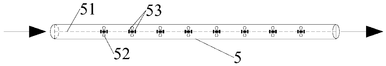
[0074] The mixing reaction device includes three gas distribution tube plates 5 sequentially arranged inside the casing along the flue gas flow direction and an electron beam generating device 6 after the last gas distribution tube plate 5 .

[0075] The flue gas flows through the dedusting device 1, the spraying device 2, the mixing reaction device and the absorption device 7 in sequence; there is an ammonia gas inlet between the flue gas inlet of the mixing reaction device and the first gas distribution tube plate 5, an...

Embodiment 2

[0081] This embodiment provides an electron beam and oxygen synergistic desulfurization and denitrification system. The electron beam and oxygen synergistic desulfurization and denitrification system includes a dust removal device 1, a spray device 2, a mixing reaction device, an absorption device 7, an oxygen supply device 4, and ammonia Air supply device 3.

[0082] The dust removal device 1 is a cyclone separator, and the spray device 2 is a spray tower.

[0083] The mixing reaction device includes two air distribution tube plates 5 sequentially arranged inside the casing along the flue gas flow direction and an electron beam generating device 6 after the last air distribution tube plate 5 .

[0084] The flue gas flows through the dedusting device 1, the spraying device 2, the mixing reaction device and the absorption device 7 in sequence; there is an ammonia gas inlet between the flue gas inlet of the mixing reaction device and the first gas distribution tube plate 5, and ...

Embodiment 3

[0090] This embodiment provides an electron beam and oxygen synergistic desulfurization and denitrification system. The electron beam and oxygen synergistic desulfurization and denitrification system includes a dust removal device 1, a spray device 2, a mixing reaction device, an absorption device 7, an oxygen supply device 4, and ammonia Air supply device 3.

[0091] The dust removal device 1 is a cyclone separator, and the spray device 2 is a spray tower.

[0092] The mixing reaction device includes six air distribution tube plates 5 sequentially arranged inside the casing along the flue gas flow direction and an electron beam generating device 6 behind the last air distribution tube plate 5 .

[0093] The flue gas flows through the dedusting device 1, the spraying device 2, the mixing reaction device and the absorption device 7 in sequence; there is an ammonia gas inlet between the flue gas inlet of the mixing reaction device and the first gas distribution tube plate 5, and...


PUM

PropertyMeasurementUnit
aspect ratioaaaaaaaaaa
clearance rateaaaaaaaaaa

Abstract

The invention relates to an electron beam-oxygen synergistic desulfurization and denitrification system and method. The system comprises a dust removal device, a spraying device, a mixed reaction device, an absorption device, an oxygen supply device and an ammonia supply device, wherein the mixed reaction device comprises at least two gas distribution pipe plates which are sequentially arranged inthe shell in a flue gas flowing direction and an electron beam generation device which is arranged behind the last gas distribution pipe plate; flue gas sequentially flows through the dust removal device, the spraying device, the mixed reaction device and the absorption device; an ammonia gas inlet is formed between a flue gas inlet of the mixed reaction device and the first gas distribution pipeplate, and is connected with the ammonia gas supply device; and an oxygen inlet is formed between the first gas distribution pipe plate and the last gas distribution pipe plate and connected with theoxygen supply device. The system can reduce the emission of ammonia gas and is beneficial for improving the desulfurization and denitrification effects of flue gas and reducing the influence of purified gas on the environment.

Description

technical field [0001] The invention relates to the technical field of flue gas treatment, relates to a desulfurization and denitrification system and method, in particular to a system and method for electron beam and oxygen synergistic desulfurization and denitrification. Background technique [0002] SO present in flue gas 2 Pollutants such as nitrogen oxides will cause serious pollution to the atmosphere. The current desulfurization methods include acid method, subtraction method, limestone-gypsum wet method, double alkali method, ammonia method and metal oxide method; the main denitrification methods include selective catalytic reduction (SCR) and selective non-catalytic reduction (SNCR) Although the SCR method can achieve high denitrification efficiency and meet the flue gas emission standards, its process and equipment system are complex and require special catalysts, and the cost of investment and operation of the entire system is relatively high; , the cost of inve...

Claims


Application Information

Patent Timeline
Patent Type & Authority Applications(China)
IPC IPC(8): B01D53/76B01D53/60B01D50/00B01D53/18
CPCB01D53/76B01D53/60B01D53/18B01D2258/0283B01D2251/102B01D2259/818B01D50/40
Inventor 胡静龄杨颖欣钟璐胡小吐刘勇杨森林
Owner GUANGDONG J TECH ENVIRONMENT SCI CO LTD
Why Eureka
Try Eureka