Flue gas desulfurization and denitrification treatment system

A desulfurization, denitrification and treatment system technology, applied in the field of flue gas desulfurization and denitrification, can solve the problems of difficult dust removal equipment, affect dust removal function, dust removal equipment falling off, etc., and achieve the effect of saving desulfurization and denitrification agent, improving desulfurization and denitrification rate, and enhancing cleaning effect.

Inactive Publication Date: 2022-03-11
徐荣俊
View PDF10 Cites 3 Cited by
  • Summary
  • Abstract
  • Description
  • Claims
  • Application Information

AI Technical Summary

Problems solved by technology

[0003] 1. When removing dust from the flue gas, the dust adhering to the dust removal equipment is usually cleaned by beating on one side. Only the way of beating on one side makes the vibration amplitude of the dust removal equipment not large, and it is difficult to make the dust removal equipment The smoke and dust on the dust removal equipment will fall off completely, and it is difficult to make all the smoke and dust on the dust removal equipment fall off only by tapping, which will easily affect the subsequent dust removal function, thereby easily reducing the dust removal efficiency of the system;
[0004] 2. When performing desulfurization and denitrification treatment on flue gas, in order to improve the desulfurization and denitrification rate, the desulfurization and denitrification agent is continuously discharged, and the consumption of desulfurization and denitrification agent is relatively large. There is a lot of waste liquid attached to it, and the waste liquid forms water droplets on the inner wall to drip, and the discharge speed is very slow, which will easily make the inner wall of the desulfurization and denitrification device stay in a wet state for a long time, which will affect the subsequent flue gas treatment.

Method used


Image

  • Flue gas desulfurization and denitrification treatment system
  • Flue gas desulfurization and denitrification treatment system
  • Flue gas desulfurization and denitrification treatment system

Examples


Embodiment Construction

[0039] The embodiments of the present invention will be described in detail below with reference to the accompanying drawings, but the present invention can be implemented in many different ways as defined and covered by the claims.

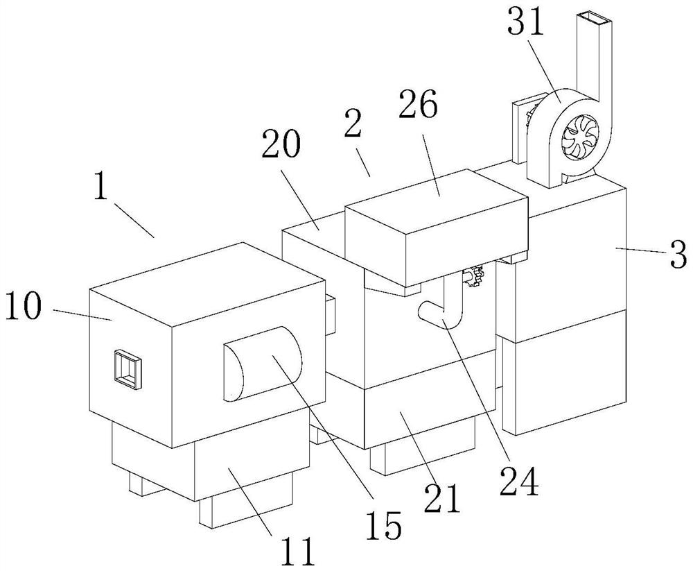
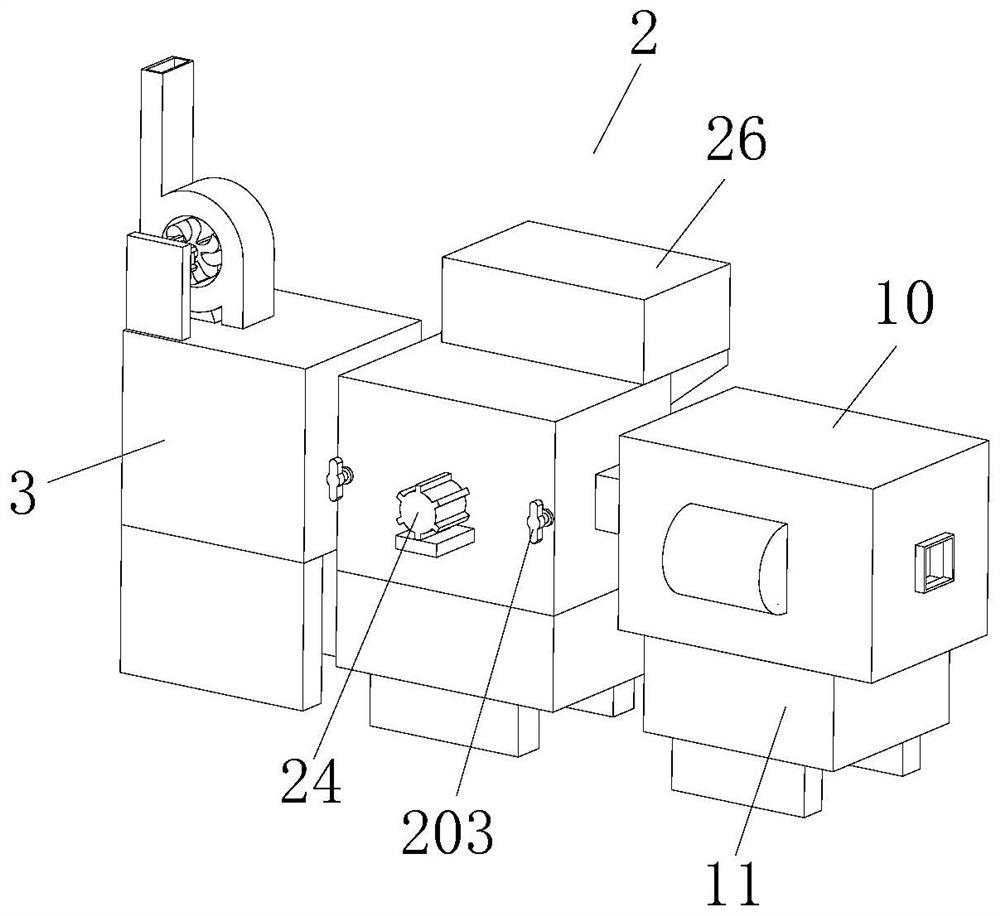
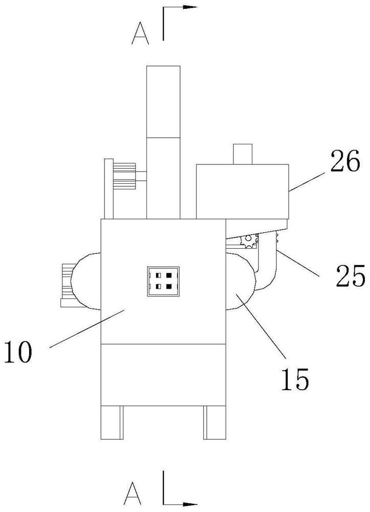
[0040] refer to figure 1 , figure 2 , Figure 4 and Figure 5 , a flue gas desulfurization and denitration treatment system, comprising a dust removal device 1, a desulfurization and denitrification device 2, a box body 3 and a flue pipe 4, the right end of the dust removal device 1 is sequentially provided with a desulfurization and denitrification device 2 and a box body 3, and the dust removal device A smoke pipe 4 is installed between the device 1 and the desulfurization and denitrification device 2, and between the desulfurization and denitrification device 2 and the box body 3. Cigarette outlet, smoke outlet place is equipped with induced draft fan 31, and the upper end of induced draft fan 31 is equipped with smoke exhaust pipe, and th...


PUM


Abstract

The invention relates to a flue gas desulfurization and denitrification treatment system, which comprises a dust removal device, a desulfurization and denitrification device, a box body and flue gas through pipes, the right end of the dust removal device is sequentially provided with the desulfurization and denitrification device and the box body, and the flue gas through pipes are arranged between the dust removal device and the desulfurization and denitrification device and between the desulfurization and denitrification device and the box body. The lower end of the box body is connected with the existing ground through a bearing plate, and a smoke exhaust port is formed in the upper end of the box body, the dust removal plate in the dust removal device improves the situation that the vibration amplitude of the dust removal plate is not large due to the fact that only one side of the dust removal plate is knocked in an existing desulfurization and denitrification treatment system, and the cleaning effect on the dust removal plate is enhanced; the desulfurization and denitrification device provided by the invention can realize the function of spraying a medicament to flue gas in all directions, improves the desulfurization and denitrification rate, can also realize the function of intermittently conveying a desulfurization and denitrification agent, and achieves the effects of saving the desulfurization and denitrification agent and reducing the cost.

Description

technical field [0001] The invention relates to the technical field of flue gas desulfurization and denitrification, in particular to a flue gas desulfurization and denitration treatment system. Background technique [0002] Flue gas desulfurization and denitrification technology is a boiler flue gas purification technology applied to the chemical industry that generates many nitrogen oxides and sulfur oxides. Currently known flue gas desulfurization and denitrification technologies include PAFP (ammonium phosphate fertilizer method), ACFP (activated carbon fiber method), pyrolusite method, electron beam ammonia method, pulse corona method, gypsum wet method, catalytic oxidation method, microbial degradation method, flue gas dust removal and desulfurization integration technology and other technologies, the existing flue gas desulfurization and denitrification treatment system is the most commonly used The most important is the flue gas desulfurization and dust removal integ...

Claims


Application Information

Patent Timeline
Patent Type & Authority Applications(China)
IPC IPC(8): B01D46/10B01D46/681B01D46/76B01D53/04B01D53/48B01D53/56B01D53/78
CPCB01D46/10B01D53/48B01D53/56B01D53/78B01D53/04B01D2253/102B01D2258/0283
Inventor 徐荣俊
Owner 徐荣俊
Why Eureka
Try Eureka