
MIG (metal inert gas) welding system

A welding system and welding process technology, applied in welding equipment, arc welding equipment, manufacturing tools, etc., can solve the problems of different welding forming operations, high heat input, breakdown of welding workpieces, etc., and achieve fast solidification speed and heat input ratio Reduced effect

Inactive Publication Date: 2016-11-09
SHANGHAI FANUC ROBOTICS
View PDF5 Cites 3 Cited by
  • Summary
  • Abstract
  • Description
  • Claims
  • Application Information

AI Technical Summary

Problems solved by technology

[0002] In the traditional welding process, because it is not continuous welding, the heat input is high, and all-position welding cannot be realized, and due to the influence of gravity, the welding forming operations at different welding positions are different, which greatly increases the The difficulty of the welding process, and it is easy to have defects such as breakdown of the welded workpiece

Method used


Image

  • MIG (metal inert gas) welding system
  • MIG (metal inert gas) welding system
  • MIG (metal inert gas) welding system

Examples


Embodiment 1

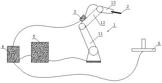
[0035] Such as figure 1 As shown, the present embodiment is a kind of MIG welding system, which can be mainly applied to the process of welding the workpiece 6, and realizes the continuous spot welding of the workpiece to be welded by combining welding robots, welding machines, robot control cabinets, etc. (Stitch Welding), which may include:

[0036] The welding robot 1 is fixed on the bottom plate or a corresponding platform near the above-mentioned workpiece (such as near the workbench for fixing the workpiece for welding), so as to use the welding robot 1 to perform subsequent welding operations on the workpiece 6; wherein , the welding robot 1 can have a bottom bracket (such as a machine hand), a boom 11 that is pivotally connected to the bracket, a small arm 12 that is pivotally connected to the boom 11, and a Wrist 13 (it should be noted that the terms of anthropomorphic limbs such as big arm, forearm and wrist here refer to the structure of the corresponding part of t...

Embodiment 2

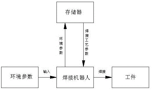
[0042] On the basis of the above-mentioned first embodiment, since welding process parameters such as welding current value, welding voltage value and welding speed value need to be input before the welding process is performed, the subsequent welding operation can be accurately realized. , that is, the selection of the above welding process parameters is the focus of the welding process using robots, which can directly affect the quality of subsequent welding. Once the input is wrong, it will even cause defects such as damage and damage to the workpiece and fixture; if it is carried out manually When inputting welding process parameters, such as figure 2 As shown, after the welding process parameters are manually input, the welding robot will directly perform corresponding welding operations on the workpiece according to the welding process parameters, that is, the quality of the operator will directly affect the quality of the welding process, which is not conducive to the q...


PUM


Abstract

The invention discloses an MIG (metal inert gas) welding system and relates to the technical field of workpiece welding. Through combination of a welding robot with equipment such as a welding machine and the like, a stitch welding technology can be performed on a workpiece, then the heat input ratio in a welding operation process can be reduced greatly, the heat accumulation is enabled to be lower, and the workpiece is not prone to burn-through; meanwhile, with adoption of spot welding, rapid solidification can be realized after welding, and then whole-position welding can be realized; further, due to high solidification speed of spot welding and smaller gravity effect, welding forming structures in difference positions are basically the same.

Description

technical field [0001] The invention relates to the field of welding, in particular to a MIG (Metal Inert Gas Welding, inert gas shielded welding) welding system. Background technique [0002] In the traditional welding process, because it is not continuous welding, the heat input is high, and all-position welding cannot be realized, and due to the influence of gravity, the welding forming operations at different welding positions are different, which greatly increases the The difficulty of the welding process, and it is easy to have defects such as breakdown of the welded workpiece. Contents of the invention [0003] In view of the above problems, the present invention provides a MIG welding system, which is applied to continuous spot welding operations on workpieces, and the MIG welding system includes: [0004] A welding robot is fixedly arranged adjacent to the workpiece, and the welding robot includes a small arm and a wrist, and a welding torch is fixed in the wrist...

Claims


Application Information

Patent Timeline
IPC IPC(8): B23K9/173B23K9/095
CPCB23K9/173B23K9/0953
Inventor 张杰孔萌金玉嵌
Owner SHANGHAI FANUC ROBOTICS
Learn More