Roller plasma 3D printing equipment and method

A 3D printing and plasma technology, applied in the direction of process efficiency improvement, additive manufacturing, additive processing, etc., can solve the problems of different specific gravity of elements, low molding efficiency, segregation, etc.

Inactive Publication Date: 2016-06-29
SINOADDITIVE MFG EQUIP CO LTD
View PDF10 Cites 6 Cited by
  • Summary
  • Abstract
  • Description
  • Claims
  • Application Information

AI Technical Summary

Problems solved by technology

[0004] First, when the centrifugal casting method is used to manufacture rolls, molten steel smelting is first required. During the smelting process, problems such as spalling of ladle refractories and insufficient deoxidation of molten steel and insufficient slag removal may cause pollution to molten steel, resulting in reduced performance or scrapping of the rolls;
[0005] Second, the elements in the centrifugal casting process are likely to cause segregation due to different specific gravity, resulting in a decrease in the performance of the roll;
[0006] Third, centrifugally cast rolls need to be heat treated after casting, the process is complex, and the existing heat treatment system is likely to cause microcracks, cracks or even scrapping of the rolls
But at present, there are three main problems in the selective electron beam rapid prototyping technology: first, the electron beam rapid prototyping technology needs a vacuum environment to form the energy source electron beam and avoid the oxidation of metal parts during the forming process
This makes the structure of the electron beam rapid prototyping equipment complex, the size of the molded parts is limited, and the molding equipment is expensive; second, the electron beam rapid prototyping technology requires a powder spreading system or a molding material supply system
This makes the structure of the electron beam rapid prototyping equipment complex, not only the size of the formed parts is limited, but also the forming efficiency is low; third, in order to ensure the mechanical properties of the parts, the electron beam rapid prototyping technology requires spherical metal powder with good fluidity
This makes SLM rapid prototyping equipment expensive to run

Method used


Image

  • Roller plasma 3D printing equipment and method
  • Roller plasma 3D printing equipment and method
  • Roller plasma 3D printing equipment and method

Examples


Embodiment 1

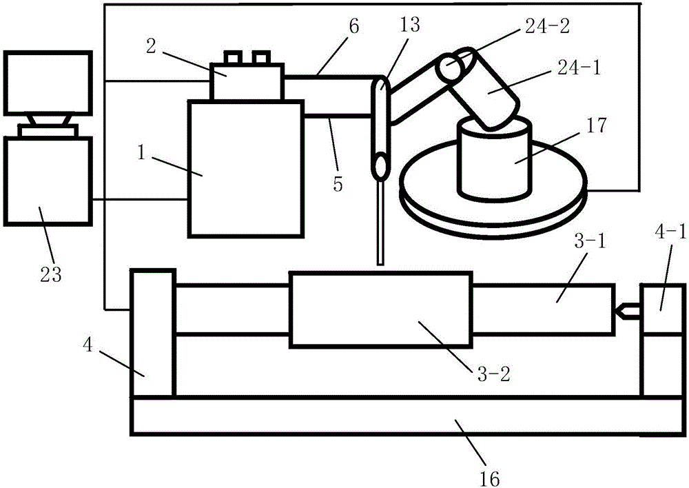
[0085] Such as figure 1 The roll plasma 3D printing equipment shown is composed of a monitoring system, a plasma beam processing system, and a horizontal printing platform for placing a roll to be formed. The roll to be formed includes a roll core 3-1 and is arranged on the roll core 3- 1. The roll body outer layer 3-2 outside the middle part, the roll body outer layer 3-2 and the roll core 3-1 are arranged coaxially. The horizontal printing table includes a horizontal support mechanism 16 and a horizontal rotation mechanism 4 that is fixedly installed on the horizontal support mechanism 16 and drives the roller core 3-1 to rotate around its central axis. The horizontal rotation mechanism 4 is located above the horizontal support mechanism 16 , the roller core 3-1 is arranged horizontally and installed on the horizontal rotation mechanism 4.

[0086] The plasma beam processing system consists of a plasma generator equipped with a shower head and used to generate plasma beams,...

Embodiment 2

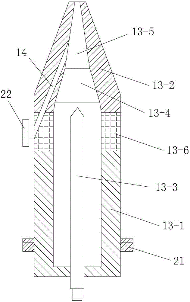
[0191] In this example, if Figure 7 As shown, the difference between the roll plasma 3D printing equipment used and the embodiment 1 is that the nozzle 13 - 5 and the powder circulation channel 14 are arranged coaxially.

[0192] In this way, after changing the direction of the plasma beam through the nozzle 13-5, the thermal load impact of the plasma jet on the anode nozzle 13-2 can be effectively reduced, and the anode ablation condition is improved. At the same time, since the nozzle 13-5 is coaxially arranged with the powder circulation channel 14, the acceleration, heating and melting process of the powder will not be affected, and the use effect is very good.

[0193] In this embodiment, the structure, connection relationship and working principle of the remaining parts of the roll plasma 3D printing equipment are the same as those in Embodiment 1.

[0194] In this embodiment, the roll plasma 3D printing method adopted is the same as that in Embodiment 1.


PUM


Abstract

The invention discloses roller plasma 3D printing equipment and method. The equipment is composed of a monitoring system, a plasma beam machining system and a horizontal printing table; the plasma beam machining system is composed of a plasma generator, a printing position adjusting device, an air supply device and a powder feeder; the printing position adjusting device comprises a horizontal movement device and a printing distance adjusting device; and the monitoring system comprises a horizontal movement controller, a temperature detecting unit, a distance detecting unit, a printing distance adjusting controller and a rotation controller, and a temperature adjusting and control device is composed of the temperature detecting unit and the printing distance adjusting controller. The method includes the steps that (1) a three-dimensional model is obtained, and hierarchy slicing treatment is carried out; (2) filling of a scanning path is carried out; (3) a printing path is obtained; and (4) layer-by-layer printing is carried out from inside to outside. The roller plasma 3D printing equipment is reasonable in design, easy and convenient to operate, high in molding efficiency and good in using effect; the molding process is directly carried out under the atmospheric environment; and molded rollers are good in quality.

Description

technical field [0001] The invention belongs to the technical field of rapid prototyping, and in particular relates to a roll plasma 3D printing equipment and method. Background technique [0002] The roll is an important part of the rolling mill in the rolling mill. It uses the pressure generated by a pair or a group of rolls to roll and roll the steel. It is mainly subjected to dynamic and static loads, wear and temperature changes during rolling. The roll mainly includes a core (also called a roll core, including a roll shaft and a roll neck) and an outer layer of a roll body (also called an outer layer or a working layer) coaxially arranged outside the core. The outer layer of the roll body and the core of the composite roll are made of different materials. The two materials are metallurgically bonded. The outer layer of the roll body is the working layer and the outer surface is the roll surface. The roll can meet the wear resistance of the roll body by the rolling mil...

Claims


Application Information

Patent Timeline
Patent Type & Authority Applications(China)
IPC IPC(8): B22F3/105B33Y30/00B33Y10/00B33Y50/02
CPCB33Y10/00B33Y30/00B33Y50/02B22F10/00B22F12/53B22F10/322B22F10/25B22F12/70B22F10/30B22F12/226Y02P10/25
Inventor 华云峰程国君郝勇魏志宇
Owner SINOADDITIVE MFG EQUIP CO LTD
Why Eureka
Try Eureka