
Method for installing Co40 cushion block on water beam in walking beam type heating furnace

A walking heating furnace and installation method technology, which is applied in the field of metallurgy, can solve the problems of water beam wrapping damage, steel billet tilting and scratching the furnace wall, bursting tubes, etc., and achieve the effect of improving bending resistance and ensuring installation stability

Active Publication Date: 2016-11-09
BENGANG STEEL PLATES
View PDF3 Cites 2 Cited by
  • Summary
  • Abstract
  • Description
  • Claims
  • Application Information

AI Technical Summary

Problems solved by technology

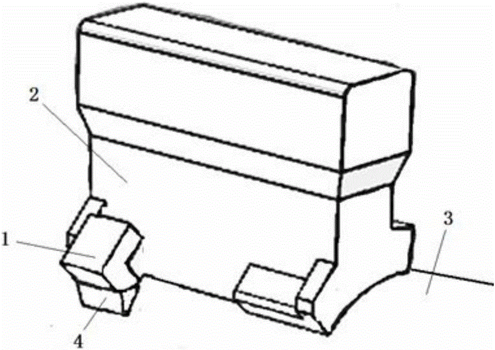
Existing structures such as figure 1 As shown, the area of ​​the second welding part 4 between the clamping block 1 and the water beam 3 is small, and the fixing strength is not enough. When the pad 2 is rubbed or bumped, it is easy to fall off.
The falling off of the pad will cause a series of serious consequences, such as: causing the steel billet to tilt and scratch the furnace wall, and sometimes even the steel billet falls into the furnace. If the steel billet squeezes into the travel groove of the moving beam, it will definitely cause major equipment accidents
If the block falls into the stroke groove of the moving beam, the water seal groove will be seriously scratched and leaked, resulting in a production stop accident
At the same time as the blocks fell off, the water girder wrapping was also damaged to varying degrees. The exposed parts of the furnace girder could easily cause major equipment accidents such as pipe bursts, and the bare pipes also had a considerable impact on the quality of the heated billet.

Method used


Image

  • Method for installing Co40 cushion block on water beam in walking beam type heating furnace
  • Method for installing Co40 cushion block on water beam in walking beam type heating furnace

Examples


Embodiment Construction

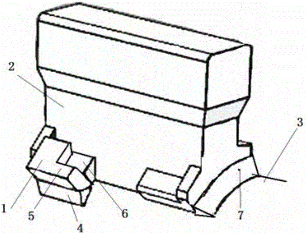
[0010] Such as figure 2 As shown, an extension 5 is added to the side of the block 1, and there is a first welding part 6 between the extension 5 and the Co40 block 2; the Co40 block 2 and the block 1 are fixed by the first welding part 6 Connection; the block 1 and the water beam 3 are connected by the second welding part 4; the first welding part 6 and the second welding part 4 can form an integral welding part; the two ends of the Co40 pad 1 and the water beam 3 pass The third welding part 7 is welded into one body;

[0011] Both ends of the Co40 pad are welded with cobalt-based surfacing electrodes, and the electrodes are baked at a temperature of 200℃~300℃ for 1-2 hours before welding; angle grinding wheels are used to remove the roots and rust to see the metallic luster at the weld, and use a DC welding machine Reverse connection (the base material is connected to the positive electrode), using 60-120 (A) current, narrow welding bead, fast welding, preferably without late...


PUM


Abstract

The invention discloses a method for installing a Co40 cushion block on a water beam in a walking beam type heating furnace. An extending part is additionally arranged on the lateral part of a clamping block; a first welding part is arranged between the extending part and the Co40 cushion block; the Co40 cushion block and the clamping block are fixedly connected through the first welding part; the clamping block and the water beam are connected through a second welding part; the first welding part and the second welding part can form an integral welding part; and two ends of the Co40 cushion block and the water beam are integrally welded. The method has the following advantages: the extending part is arranged on the side of a force bearing point of the clamping block, and the cushion block is welded with the same side of the force bearing point of the clamping block, so that the fracture resistance and the bending resistance of the clamping block can be greatly improved; and in addition, the difficulty in welding between the Co40 cushion block and the water beam is overcome, and the installing stability of the Co40 cushion block is further ensured.

Description

Technical field [0001] The invention relates to the technical field of metallurgy, in particular to a method for installing a water beam cushion block. Background technique [0002] The water beam pad of the heating furnace is fixed by a clip, the material of the clip 1Cr18Ni9Ti is welded to the water beam, and the material of the pad is Co40 and the water beam is not welded. The existing structure is like figure 1 As shown, the area of ​​the second welding part 4 between the block 1 and the water beam 3 is small, and the fixing strength is insufficient. When the pad 2 is rubbed or collided, it is easy to fall off. The falling off of the cushion blocks will cause a series of serious consequences, such as: causing the billet to tilt and scratch the furnace wall, and sometimes even the billet falls into the furnace. If the billet squeezes into the moving beam travel groove, it will definitely cause a major equipment accident. If the cushion block falls into the travel groove of th...

Claims


Application Information

Patent Timeline
IPC IPC(8): B23K37/00B23K9/02F27B9/30
CPCB23K9/02B23K37/00F27B9/30
Inventor 杨奎
Owner BENGANG STEEL PLATES
Learn More