Power battery high-applicability nondestructive automatic clamping apparatus

A power battery and applicability technology, which is applied in the field of automatic clamping fixture device, can solve the problems of battery shell damage, high cost, and inability to absorb the battery, and achieve the effects of ensuring stability, improving production efficiency, and high flexibility

Active Publication Date: 2016-11-09
镇江科信动力系统设计研究有限公司
View PDF7 Cites 22 Cited by
  • Summary
  • Abstract
  • Description
  • Claims
  • Application Information

AI Technical Summary

Problems solved by technology

[0002] At present, the power battery production equipment on the market has a high degree of automation, and automatic grasping mechanisms are often used for battery loading and unloading operations. Common methods include direct grasping of the battery by a manipulator, or suction of the battery by means of a suction cup, and the manipulator exerts force on a small area of ​​the battery. When clamping, it is easy to cause damage to the battery case, and the suction cup cannot absorb a large-volume battery. In addition, there are many production processes for power batteries. Each process will tailor the fixture tooling according to the battery specifications and processing methods. The same model Fixtures are different in different processes, and the overall cost is relatively high

Method used


Image

  • Power battery high-applicability nondestructive automatic clamping apparatus
  • Power battery high-applicability nondestructive automatic clamping apparatus
  • Power battery high-applicability nondestructive automatic clamping apparatus

Examples


Embodiment Construction

[0015] Below in conjunction with accompanying drawing and specific embodiment, further illustrate the present invention, should be understood that these embodiments are only for illustrating the present invention and are not intended to limit the scope of the present invention, after having read the present invention, those skilled in the art will understand various aspects of the present invention Modifications in equivalent forms all fall within the scope defined by the appended claims of this application.

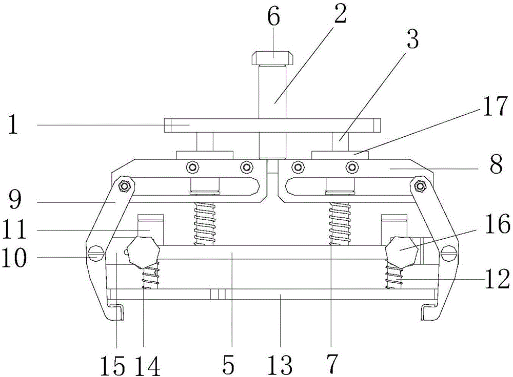
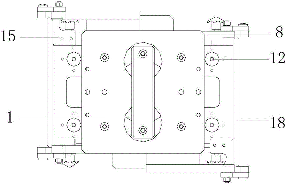
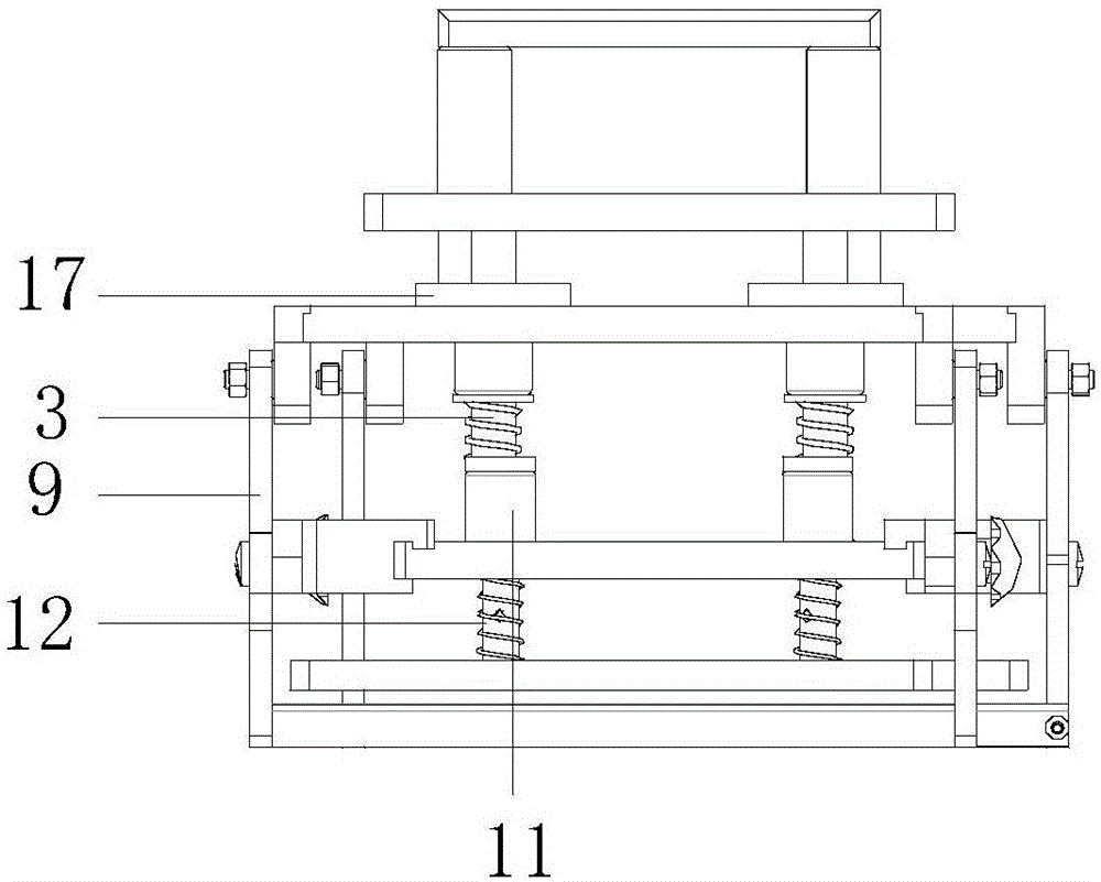
[0016] as attached Figures 1 to 4 As shown, a high applicability non-damage automatic clamping fixture device for power batteries, including a fixed plate 1, a moving guide post 2, a pressing guide post 3, a moving plate 4, a supporting plate 5, a connecting rod 6, and a pressing guide post Spring 7, jaw guide frame 8, jaw 9, shaft screw 10, guide column linear bearing 11, pressure plate guide column 12, battery pressure plate 13, pressure plate guide column spring 14, ...


PUM


Abstract

The invention discloses a power battery high-applicability nondestructive automatic clamping apparatus which comprises a fixed plate, movable guide posts, a press guide post, a movable plate, a supporting plate, a connecting rod and a clamping jaw guide frame, wherein the upper part of the movable plate is provided with the at least two movable guide posts; the movable guide posts respectively penetrate through holes arranged in the fixed plate, and the upper ends are connected through the connecting rod; the press guide post penetrates through the movable plate, the upper end is connected with the fixed plate, and the lower end is connected with the supporting plate; a press guide post spring is sheathed on the press guide post; the press guide post spring is positioned between the movable plate and the supporting plate; the clamping jaw guide frame is installed on the movable plate; the clamping jaw guide frame is connected with a clamping jaw; and the clamping jaw comprises two sections, and is movably connected to the supporting plate through a shaft position screw. The apparatus can be used for quickly and flexibly clamping the batteries without destructing the batteries, can reshape the batteries, and is suitable for different battery models.

Description

technical field [0001] The invention relates to the field of power battery manufacturing, in particular to a highly adaptable and non-damaging automatic clamping device for power batteries. Background technique [0002] At present, the power battery production equipment on the market has a high degree of automation, and automatic grasping mechanisms are often used for battery loading and unloading operations. Common methods include direct grasping of the battery by a manipulator, or suction of the battery by means of a suction cup, and the manipulator exerts force on a small area of ​​the battery. When clamping, it is easy to cause damage to the battery case, and the suction cup cannot absorb a large-volume battery. In addition, there are many production processes for power batteries. Each process will tailor the fixture tooling according to the battery specifications and processing methods. The same model Fixtures are different in different processes, and the overall cost i...

Claims


Application Information

Patent Timeline
Patent Type & Authority Applications(China)
IPC IPC(8): B25J15/08B25J11/00B25J15/10B25J9/08B65G47/90
CPCB25J9/08B25J11/00B25J15/08B25J15/10B65G47/901
Inventor 吉跃华袁伟宏杜隆
Owner 镇江科信动力系统设计研究有限公司
Why Eureka
Try Eureka