Supercharge Your Innovation With Domain-Expert AI Agents!

Vacuum feeding device

A technology of vacuum feeding and powder bucket, which is applied in transportation and packaging, conveying bulk materials, conveyors, etc., can solve the problems of unsatisfactory elevator, laborious feeding, time-consuming and laborious feeding operation, etc.

Inactive Publication Date: 2018-02-16
ZHEJIANG FUTURE MACHINERY
View PDF8 Cites 0 Cited by
  • Summary
  • Abstract
  • Description
  • Claims
  • Application Information

AI Technical Summary

Problems solved by technology

Manual feeding is generally labor-intensive, and the dust is seriously flying. Generally, this feeding method is not adopted; the hoist feeding has relatively high requirements for the floor height and area of ​​the workshop, and a separate operator must operate the hoist during operation, which is not ideal; traditional The vacuum feeding is easy to cause the filter system to be blocked, and the vacuum force is unstable, which leads to the failure of feeding
For this reason, the applicant applied for an invention patent with the patent number 201410489077.X on September 23, 2014, and the patent name is "Dry Granulator Negative Pressure Feeding Device". The technology provided by this patent, especially the design with arch elimination The conveying pipe (connector part) can well solve the vacuum feeding of powder with poor fluidity, but it is obviously not suitable for powder with good fluidity, and the powder with good fluidity will flood into the arch elimination in large quantities The conveying pipe is blocked, and the raw powder barrel (storage barrel) needs to be lifted before each loading, and the loading operation is time-consuming and laborious

Method used


Image

  • Vacuum feeding device
  • Vacuum feeding device
  • Vacuum feeding device

Examples


Embodiment Construction

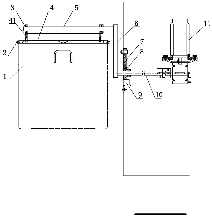
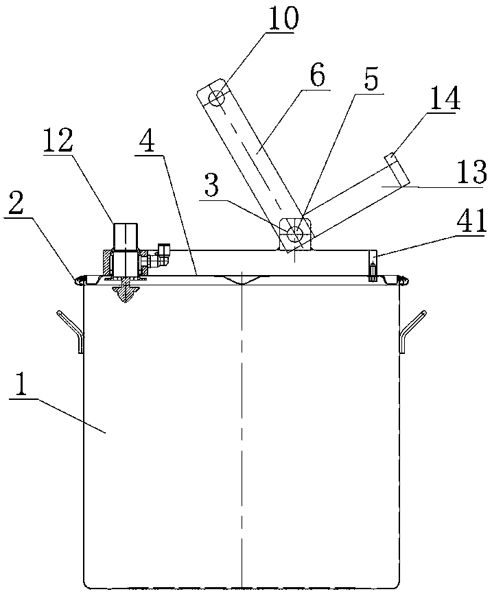
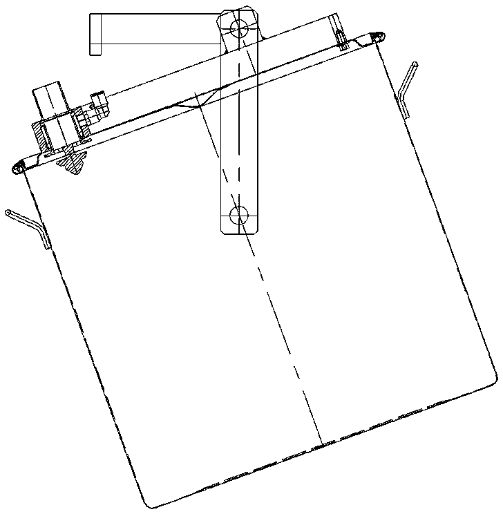
[0015] As shown in the figure, the vacuum feeding device of the present invention includes a raw powder barrel 1, the barrel mouth of the raw powder barrel 1 is connected to the barrel cover 4 through a clamp 2, and the barrel cover 4 is equipped with a delivery pipe 12 with an arch-removing design to transport The tube 12 is located on the left side of the bung 4, and the center of the bung 4 is provided with a lifting lug hole 3 to the right, and a rotating shaft 5 is arranged in the lifting lug hole 3, and the rotating shaft 5 is fixedly connected to the swing rod 6, and the swing rod 6 is vertically The plane swings in a circle, the swing rod 6 is connected with the transmission shaft 10, and the transmission shaft 10 is driven by the servo motor 11. When the transmission shaft 10 rotates, the swing rod 6 and the rotating shaft 5 drive the raw powder bucket 1 to lift, and the rotating shaft 5 is fixed on the auxiliary The rod 13, the auxiliary rod 13 and the swing rod 6 are...


PUM


Abstract

The invention discloses a vacuum feeding device. The vacuum feeding device comprises a raw powder bucket, an opening of the raw powder bucket is connected with a bucket cover through a hoop, and an arch-removing conveying pipe is installed on the bucket cover. The vacuum feeding device is characterized in that the conveying pipe is located on the left side edge of the bucket cover, a lug hole is formed in the part, deviated to the right from the center, of the bucket cover, a rotating shaft is rotationally installed in the lug hole, the rotating shaft is fixedly connected to a swing rod, the swing rod carries out circumferential swing in the vertical plane and is connected with a transmission shaft, the transmission shaft is driven by a servo motor and drives the raw powder bucket to be lifted through the swing rod and the rotating shaft in rotation, an auxiliary rod is fixedly installed on the rotating shaft, and a buckling terminal is arranged at the end of the auxiliary rod. After the swing rod swings upwards to make the center of the rotating shaft located on the upper left part of the center of the transmission shaft, the auxiliary rod is in contact with the bucket cover, the buckling terminal downwards enters a buckling groove formed in the bucket cover, and the auxiliary rod continues to swing along with the swing rod to push the raw powder bucket to overturn. By means of the vacuum feeding device, feeding operation is convenient, intelligent tracking feeding of various powder materials with different liquidities can be achieved, and the smooth feeding process and high feeding efficiency are ensured.

Description

technical field [0001] The invention relates to a dry granulator, in particular to a vacuum feeding device for the dry granulator. Background technique [0002] At present, the vast majority of dry granulators use vacuum feeding, elevator feeding, and manual feeding. Manual feeding is generally labor-intensive, and the dust is seriously flying. Generally, this feeding method is not adopted; the hoist feeding has relatively high requirements for the floor height and area of ​​the workshop, and a separate operator must operate the hoist during operation, which is not ideal; traditional Vacuum feeding is easy to cause blockage of the filter system, and the vacuum force is unstable, resulting in failure to feed. For this reason, the applicant applied for an invention patent with the patent number 201410489077.X on September 23, 2014, and the patent name is "Dry Granulator Negative Pressure Feeding Device". The technology provided by this patent, especially the design with arch ...

Claims


Application Information

Patent Timeline
Patent Type & Authority Patents(China)
IPC IPC(8): B65G53/24B65G53/36
CPCB65G53/24B65G53/36
Inventor 林德平谢斌斌
Owner ZHEJIANG FUTURE MACHINERY
Features
  • R&D
  • Intellectual Property
  • Life Sciences
  • Materials
  • Tech Scout
  • Unparalleled Data Quality
  • Higher Quality Content
  • 60% Fewer Hallucinations
Learn More