Spliced bridging structure and building method thereof

A splicing and connecting structure technology, applied in the field of transportation, can solve the problems of reducing the degree of congestion and abnormal congestion of the horizontal main road, and achieve the effect of reducing traffic congestion, reducing the impact of traffic, and simple structure

Active Publication Date: 2016-11-09
山东宏阳型材科技股份有限公司
View PDF6 Cites 2 Cited by
  • Summary
  • Abstract
  • Description
  • Claims
  • Application Information

AI Technical Summary

Problems solved by technology

[0002] In current urban traffic, if the vertical and horizontal roads are branch roads, that is, the traffic flow is small, most of the traffic lights are designed at the intersection; For various forms of overpasses, a small number of traffic lights are designed at the intersections. If the way of designing viaducts or overpasses is adopted, this process will inevitably require traffic control at the intersections of the vertical and horizontal main roads, and even need to be temporarily blocked. However, the vertical and horizontal road systems Main roads, because the roads are relatively open, and the construction will be carried out in sections, that is, when the construction is on the horizontal main road, the construction of the vertical main

Method used


Image

  • Spliced bridging structure and building method thereof
  • Spliced bridging structure and building method thereof
  • Spliced bridging structure and building method thereof

Examples


Embodiment Construction

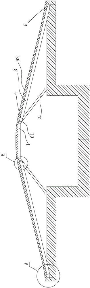
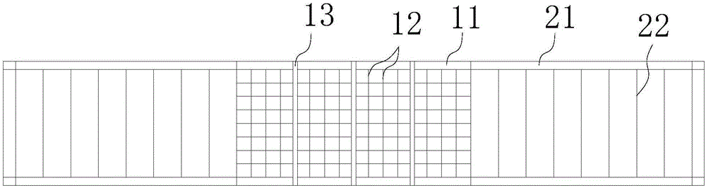
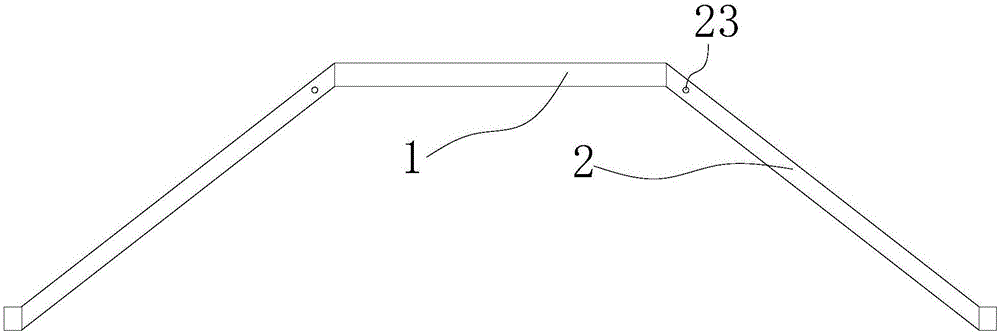
[0023] Such as Figure 1~6 As shown: it includes at least one set of arch bridge structures and slope structures arranged at the front and rear of the arch bridge structures and correspondingly connected with the arch bridge structures. The bridge frame 2 is connected as a whole, and the subgrade section 1 is connected with the bridge frame 2 to form an arch structure. The two ends of the bridge frame 2 are erected on both sides of the passage perpendicular to the arch bridge structure; The force is guided to the ground through the bridge frame. On the other hand, due to the small area of ​​the roadbed section, the sum of the forces exerted by the vehicle on the roadbed section is also small.

[0024] The sloping plate structure includes a slope subgrade section 3 and an overlapping structure 4 arranged on the front side of the slope subgrade section 3. The connection structure 4 is built on the bridge frame 2 and fixedly connected with the bridge frame 2, and the limit struc...


PUM


Abstract

The invention relates to a spliced bridging structure and a building method thereof. The spliced bridging structure comprises at least one group of arch bridge structures and slope structures, wherein the slope structures are arranged at the front and rear parts of the arch bridge structures and are correspondingly connected with the arch bridge structures. The building method comprises the following steps: (a) fixing at least one group of arch bridge structures at a transverse channel; (b) sending oblique plate structures in quantity correspondence with the arch bridge structures to the front and rear sides of the arch bridge structures, and fixing; (c) forming a groove in a pavement, and fixedly embedding a limiting structure into the groove; (d) pouring cement into gaps among the groove structure, the arch bridge structures and the oblique plate structures, and paving asphalt; and (e) directly digging a sunken and arc-shaped longitudinal channel in the transverse pavement. The spliced bridging structure and the building method have the advantages that (a) the construction speed is high, so that the influence to the traffic is reduced; (2) the structure is simple, the cost is relatively low, the integral strength is improved by virtue of a steel structure, and the strength is improved by the pouring of concrete; and (3) the urban traffic pressure can be effectively alleviated, and the situation of traffic jams can be avoided or reduced.

Description

technical field [0001] The invention relates to the traffic field, in particular to a spliced ​​bridging structure with fast construction and simple structure and its erection method. Background technique [0002] In current urban traffic, if the vertical and horizontal roads are branch roads, that is, the traffic flow is small, most of the traffic lights are designed at the intersection; For various forms of overpasses, a small number of traffic lights are designed at the intersections. If the way of designing viaducts or overpasses is adopted, this process will inevitably require traffic control at the intersections of the vertical and horizontal main roads, and even need to be temporarily blocked. However, the vertical and horizontal road systems Main roads, because the roads are relatively open, and the construction will be carried out in sections, that is, when the construction is on the horizontal main road, the construction of the vertical main road will be reduced, s...

Claims


Application Information

Patent Timeline
IPC IPC(8): E01D21/00
CPCE01D21/00
Inventor 郑勤民
Owner 山东宏阳型材科技股份有限公司
Why Eureka
Try Eureka