A bridge erection construction method using a 900-ton beam moving machine to load beams on bridge deck beam trucks

A construction method and beam-moving machine technology, applied in bridges, bridge construction, erection/assembly of bridges, etc., can solve the problems of capital occupation, increase of company operating costs, waste of resources, etc., to avoid blind investment and reduce the company's financial pressure , The effect of reducing equipment investment costs

Active Publication Date: 2018-02-06
中铁十七局集团第三工程有限公司
View PDF6 Cites 0 Cited by
  • Summary
  • Abstract
  • Description
  • Claims
  • Application Information

AI Technical Summary

Problems solved by technology

[0004] At present, in the construction process of high-speed railway bridge erection, a set of 900-ton beam-moving machine and two sets of 450-ton beam-lifting machine are required to lift the beam onto the bridge and load the beam to the beam-transporting vehicle when transporting the beam. All kinds of construction equipment will cause a lot of waste of resources, occupy funds, and increase the company's operating costs. How to rationally, flexibly, and integrate existing resources without blindly purchasing equipment is a practical issue that construction companies need to consider

Method used


Image

  • A bridge erection construction method using a 900-ton beam moving machine to load beams on bridge deck beam trucks
  • A bridge erection construction method using a 900-ton beam moving machine to load beams on bridge deck beam trucks
  • A bridge erection construction method using a 900-ton beam moving machine to load beams on bridge deck beam trucks

Examples


Embodiment Construction

[0022] The present invention will be further described in detail below in conjunction with the accompanying drawings and specific embodiments.

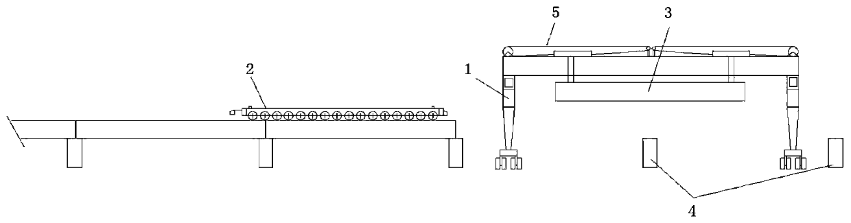
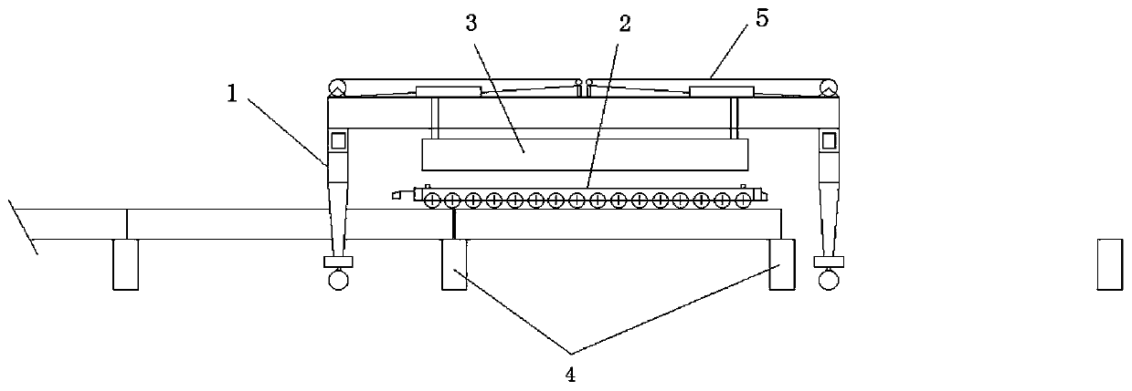
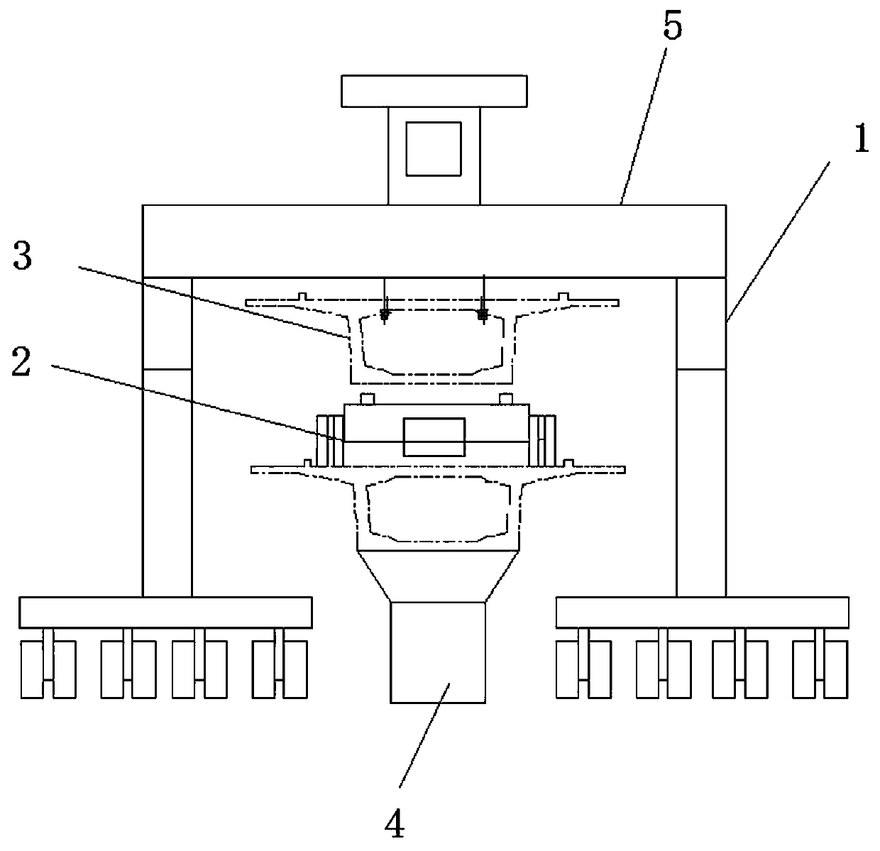
[0023] In the construction process of high-speed railway bridge erection, when the beam yard is located on the side of the bridge, a set of 900-ton beam shifting machine and two sets of 450-ton beam lifting machine are required to lift the beam to the bridge and load the beam to the beam truck when transporting the beam. In the absence of a 450-ton beam lifting machine, using this bridge erection construction method and the existing 900-ton beam moving machine in the beam yard can conveniently and labor-savingly load beams to the bridge deck beam transport vehicle. Since the height of the existing 900-ton beam-moving machine is not enough, this method first needs to transform the 900-ton beam-moving machine according to the height of the bridge deck, that is, erect the height-increasing joints on the legs of the beam-moving machine, an...


PUM


Abstract

The invention discloses a bridge construction method adopting a 900-tonnage girder transferring machine for loading girders onto a bridge girder transporting vehicle and relates to the technical field of erection of high-speed railway bridges. The bridge construction method comprises the following steps that heightening sections are installed on supporting legs of the 900-tonnage girder transferring machine according to the height of a bridge pier; a bridge girder erection machine and the girder transporting vehicle are spliced in place on a bridge floor; two holes are reserved in one end of a bridge, erection is not conducted at the end, and bridging is sequentially carried out forwards from the end with the holes to the other end of the bridge; the 900-tonnage girder transferring machine lifts the girders, travels to the position coinciding with the path of the bridge floor, turns by 90 degrees, and travels to the girder loading position of the girder transporting vehicle by stretching across of the bridge floor to load the girders onto the girder transporting vehicles; and the 900-tonnage girder transferring machine retracts after the girders are loaded, the girder transporting vehicle starts to transport the girders, and the bridging is carried out forwards. According to the bridge construction method, the girders are loaded onto the girder transporting vehicle on the bridge floor by means of the existing 900-tonnage girder transferring machine, two 450-tonnage girder lifting machines and ground infrastructures such as auxiliary rails are omitted, resources are fully and flexibly utilized, equipment investment cost is reduced, the capital burden of a company is relieved, and meanwhile another solution to bridge erection is provided.

Description

technical field [0001] The invention relates to the technical field of high-speed railway bridge erection, in particular to a bridge erection construction method using a 900-ton beam moving machine to load beams on bridge deck beam transport vehicles. Background technique [0002] With the rapid and steady development of my country's infrastructure construction, China's railways have entered a stage of leapfrog development. Due to the terrain and geographical location, the erection of large bridges and extra large bridges has gradually increased, and many problems are also faced during the construction process. The specifications of the existing construction machinery and equipment are not suitable, such as high construction costs. [0003] In terms of railway construction, one of the key issues that needs to be solved first is how to meet the growing demand with lower construction costs, higher construction efficiency, and high-quality completion of construction goals. At p...

Claims


Application Information

Patent Timeline
Patent Type & Authority Patents(China)
IPC IPC(8): E01D21/06
CPCE01D21/06
Inventor 乐锋孙修德曹会芹魏文柱张生全张孝儒閤鹏
Owner 中铁十七局集团第三工程有限公司
Why Eureka
Try Eureka