
Reinforcement Cage Main Reinforcement Locator and Its Application Method

A reinforcement cage and locator technology, which is applied in construction, sheet pile walls, foundation structure engineering, etc., to achieve the effects of avoiding steel reinforcement injuries, shortening processing time, and improving manufacturing accuracy

Active Publication Date: 2018-03-16
SHANDONG ELECTRIC POWER TRANSMISSION & SUBSTATION ENG CO
View PDF4 Cites 0 Cited by
  • Summary
  • Abstract
  • Description
  • Claims
  • Application Information

AI Technical Summary

Problems solved by technology

[0003] In order to overcome the problems existing in the prior art, the present invention provides a steel cage main bar locator and its use method, which not only improves the manufacturing accuracy of the steel cage, but also greatly improves the efficiency of the steel cage production, reduces manual labor, and avoids Prevented the situation where multiple people's operations did not cooperate well and caused steel bars to injure people

Method used


Image

  • Reinforcement Cage Main Reinforcement Locator and Its Application Method
  • Reinforcement Cage Main Reinforcement Locator and Its Application Method
  • Reinforcement Cage Main Reinforcement Locator and Its Application Method

Examples


Embodiment Construction

[0026] The following is attached Figure 1-6 The features and principles of the present invention are described in detail, and the examples given are only used to explain the present invention, not to limit the protection scope of the present invention.

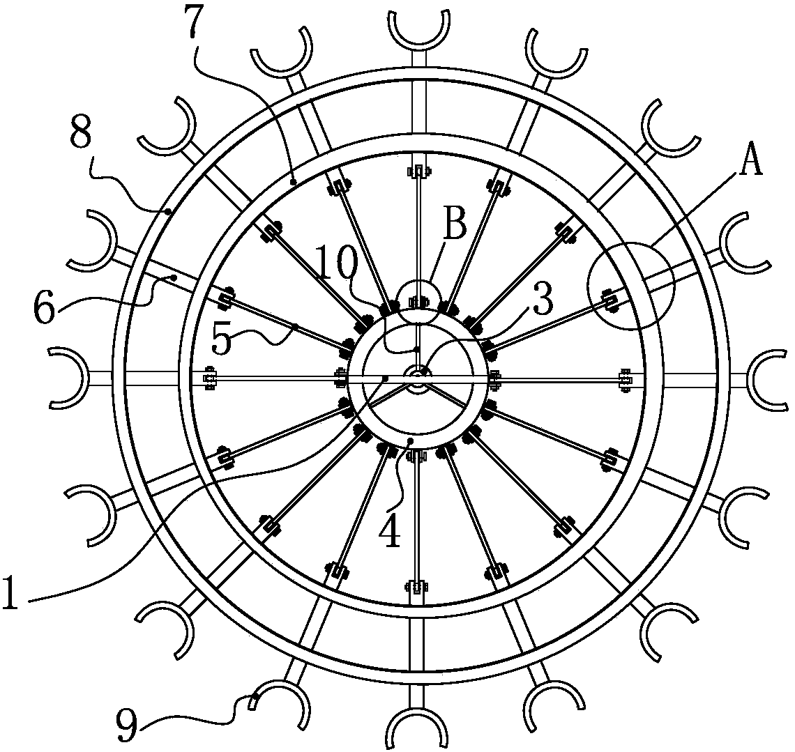
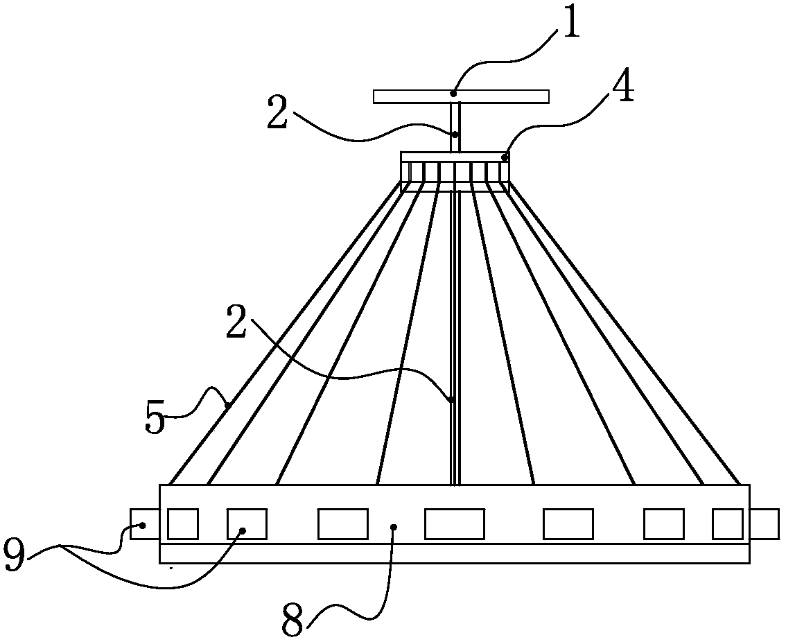
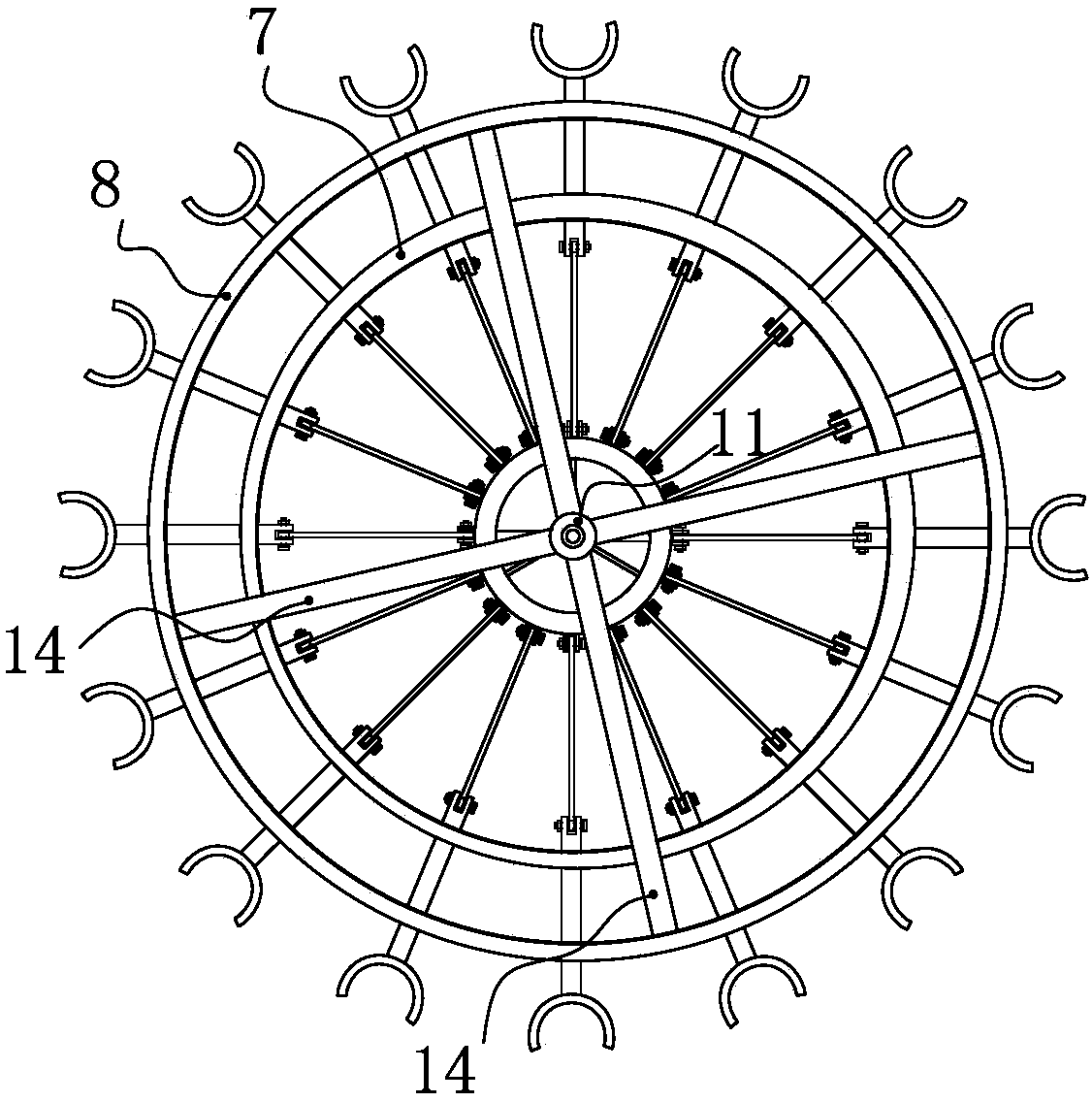
[0027] Such as Figure 1-3 As shown, the invention includes an operating handle 1, a lead screw 2, a screw nut 3, an active support ring 4, a support rod 5, a ejector rod 6, an inner support frame 7 for ejector rod positioning, an outer support frame 8 for ejector rod positioning, and a positioning support mold 9. The main reinforcement cage locators are all made of stainless steel.

[0028] The operating handle is located on the top of the locator and is fixedly connected to the top of the lead screw as a whole. The upper part of the lead screw is connected with the screw nut. Turning the operating handle drives the lead screw to rotate to drive the screw nut to move along the lead screw. The operating handle is provided ...


PUM


Abstract

The invention provides a main reinforcement locator for a reinforcement cage and a use method of the main reinforcement locator. An operation handle drives driving supporting rings to move up and down through matching between a lead screw and a screw nut. The driving supporting rings are connected with respective corresponding ejector rods through a plurality of supporting rods which are arranged in an inclined and divergent manner. The top of each supporting rod is hinged to the outer circumferential face of the corresponding driving supporting ring. The bottom of each supporting rod is hinged to one end of the corresponding ejector rod which is horizontally arranged. The ejector rods sequentially penetrate a round inner ejector rod locating supporting frame and a round outer ejector rod locating supporting frame from inside to outside. The other end of each ejector rod extends out of the outer ejector rod locating supporting frame and is fixedly connected with a locating supporting formwork. The locating supporting formwork is clamped to main reinforcements of the reinforcement cage. The ejector rods can horizontally move in the radial direction of the inner ejector rod locating supporting frame and the outer ejector rod locating supporting frame. The main reinforcement locator for the reinforcement cage solves the problems that in the manufacturing process of the reinforcement cage, the manufacturing precision is difficult to ensure, and multi-person operation is needed, improves the manufacturing precision of the reinforcement cage, shortens the machining time and avoids the situation that because cooperation is poor during multi-person operation, people are hurt by the reinforcements.

Description

technical field [0001] The invention relates to the technical field of steel cage production in cast-in-situ pile foundation construction section in power transmission line engineering, in particular to a steel cage main reinforcement locator and a method for using the same. Background technique [0002] After the cast-in-place pile foundation of the transmission line project is bored, the reinforcement cage must be manufactured and installed; currently, the reinforcement cage is manufactured by hand, so the manufacturing accuracy is difficult to guarantee and requires multiple people to operate. It is difficult to guarantee the production accuracy in the production process of the steel cage and requires multiple people to operate, the production precision is low, and the processing time is long. There is no good solution yet. Contents of the invention [0003] In order to overcome the problems existing in the prior art, the present invention provides a steel cage main ba...

Claims


Application Information

Patent Timeline
Patent Type & Authority Patents(China)
IPC IPC(8): E02D5/34
CPCE02D5/34
Inventor 刘仙仰徐海涛李永年徐苏民李凯季道广
Owner SHANDONG ELECTRIC POWER TRANSMISSION & SUBSTATION ENG CO
Learn More