Truss girder, combination beam using truss girders and combination floor system using truss girders

A technology of truss beams and composite beams, which is applied in the field of composite floors, can solve problems such as difficulty in realizing industrialized production, uneven bottom of the floor, and uneven bottom of the floor, and achieve the effects of improving dust, light weight, and improving performance

Active Publication Date: 2016-11-09
杭州材智建筑科技有限公司
View PDF10 Cites 7 Cited by
  • Summary
  • Abstract
  • Description
  • Claims
  • Application Information

AI Technical Summary

Problems solved by technology

[0003] Among them, the cast-in-place concrete slab has the advantages of good integrity, high rigidity, and low cost, but it needs to carry out cumbersome and complicated on-site temporary formwork engineering (the on-site temporary formwork engineering refers to the vertical support column frame before the concrete slab is poured, and the vertical Lay beam brackets and wooden formwork on the supporting column frame), the construction speed is slow, the cycle is long, and it is difficult to realize industrial production, etc.
[0004] Although the construction speed of concrete prefabricated slabs is fast and most formwork supports can be eliminated, the disadvantages are that the floor slabs are poor in integrity, and one-way stress is easy to produce cracks, which is not suitable for areas with high seismic intensity. In addition, its impermeability also poor
[0005] Although the construction speed of the profiled steel plate concrete composite floor is fast and the overall rigidity is good, the cost is high. It has the disadvantages of unequal two-way rigidity in the plane and uneven bottom surface of the floor, and the bottom of the floor is uneven, which requires ceiling treatment

Method used


Image

  • Truss girder, combination beam using truss girders and combination floor system using truss girders
  • Truss girder, combination beam using truss girders and combination floor system using truss girders
  • Truss girder, combination beam using truss girders and combination floor system using truss girders

Examples


Embodiment 1

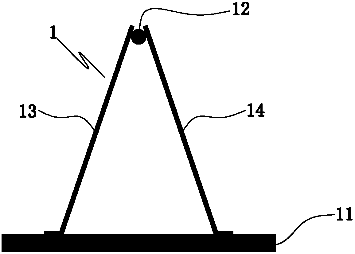
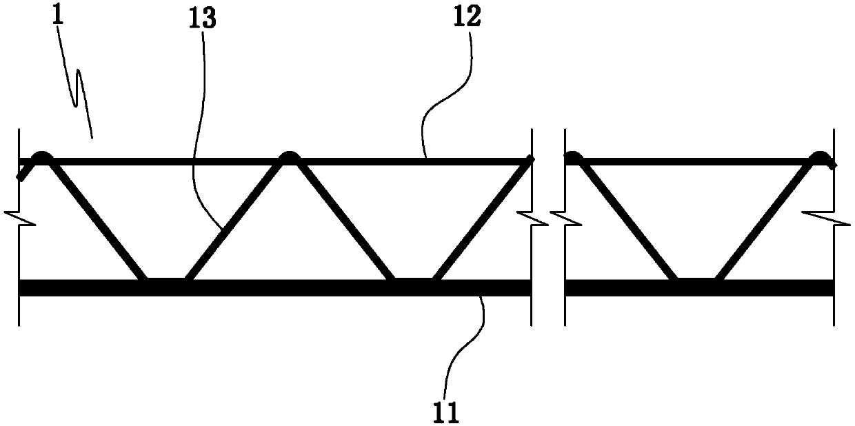
[0033] Embodiment 1: as figure 1 , figure 2 As shown, a truss girder includes a lower chord 11 , an upper chord 12 located above the lower chord, and a connecting web connecting the upper chord and the lower chord. The lower chord plate is parallel to the upper chord member. The lower chord board is steel plate or concrete prefabricated board. The upper chord members are steel bars or steel pipes or H-shaped, I-shaped, and channel-shaped steel members.

[0034] The web bar includes a left web bar 13 and a right web bar 14, and the left web bar and the right web bar are located on opposite sides of the upper chord member. The left abdominal rod and the right abdominal rod are symmetrically distributed on both sides of the upper chord member. The upper chord member, the left web member, the right web member and the lower chord plate form a truss beam with a triangular cross section.

[0035] The left abdominal bar and the right abdominal bar are arranged in waves. The upp...

Embodiment 2

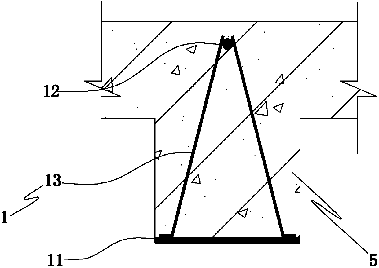
[0037] Embodiment 2: as image 3 As shown, a composite beam is composed of concrete and a truss beam 1 . For the specific structure of the truss girder in this embodiment, refer to Embodiment 1. The lower chord plate of the truss girder is also provided with auxiliary shear connectors. The auxiliary shear connectors are steel bars or studs or anchors or steel pipes or H-beams or I-beams or channel steels. The upper chord member of the truss beam, the connecting web member and the auxiliary shear connector are located inside the composite beam 5 . The lower chord plate of the truss beam is located on the lower surface of the composite beam, and the lower chord plate is connected with the concrete through the connecting web. The upper chord member is used to bear the upper tension of the composite beam, the connecting web is used to bear the shear force of the composite beam, and the lower chord is used to bear the lower tension of the composite beam.

Embodiment 3

[0038] Embodiment 3: as Figure 4 , Figure 5 As shown, a composite floor includes a main frame beam 2 , a truss beam 1 , a number of light plate bottom forms 3 and a concrete floor 4 . For the specific structure of the truss girder in this embodiment, refer to Embodiment 1. The truss beam is supported on the main frame beam through the lower chord plate 11 . The truss beams are located between the lightweight sheet bottom forms. The concrete floor slab is located above the bottom formwork of the lightweight slab, and the concrete floor slab and the truss beams are integrated into a whole. In actual construction: after the concrete floor is poured, the truss beam and concrete are combined to form a steel-concrete composite beam, and the composite beam and the cast-in-place concrete slab are combined to form an integral concrete floor, which is combined with a lightweight plate base form to become Composite floors with integral structure, and work together.

[0039] For any ...


PUM


Abstract

The invention discloses a truss girder, a combination beam using truss girders and a combination floor system using truss girders. The truss girder comprises a lower chord plate, an upper chord member located above the lower chord plate and a connecting web member connecting the upper chord member with the lower chord plate. The combination beam is composed of the truss beams and concrete, and the steel and concrete combination beam is formed through construction. The combination floor system comprises main frame beams, truss beams, a plurality of light plate bottom molds and concrete floors, wherein the truss beams are supported on the main frame beams through lower chord plates, the light plate bottom molds are located between the truss beams, and the concrete floors are located on the light plate bottom molds. The whole floor system construction process does not need supporting, and the truss beams are used for bearing construction loads. The truss beams and the concrete are combined into the steel structure-concrete combined beam which is hidden in the floor system to serve as a hidden ribbed beam and bear the loads in the use stage. The combination floor system has the advantages of being low in cost, high in speed, excellent in heat preservation and noise isolation performance, light, high in strength, environmentally friendly, convenient to industrialize and the like.

Description

technical field [0001] The invention relates to the field of building structures, in particular to a truss beam, a composite beam using the truss beam and a composite floor using the truss beam. Background technique [0002] At present, in the field of application of floor technology in building structures, the main types of floors include cast-in-place concrete slabs, prefabricated concrete slabs, laminated slabs, and profiled steel plate concrete composite slabs. [0003] Among them, the cast-in-place concrete slab has the advantages of good integrity, high rigidity, and low cost, but it needs to carry out cumbersome and complicated on-site temporary formwork engineering (the on-site temporary formwork engineering refers to the vertical support column frame before the concrete slab is poured, and the vertical Lay beam brackets and wooden formwork on the support column frame), the construction speed is slow, the cycle is long, and it is difficult to realize industrialized p...

Claims


Application Information

Patent Timeline
Patent Type & Authority Applications(China)
IPC IPC(8): E04C5/065E04C3/293E04B5/38
CPCE04B5/38E04C3/293E04C5/065E04C5/0656
Inventor 张皓周金政韩祎韧楼强辉黄金桥
Owner 杭州材智建筑科技有限公司
Why Eureka
Try Eureka