Novel electrically-controlled oil injector

An electronically controlled fuel injection, a new type of technology, used in machines/engines, fuel injection devices, engine components, etc., can solve the problem of reduced opening or closing speed of the nozzle needle valve, short fuel injection duration, and increased fuel injection nozzles. Needle valve closing resistance and other problems, to achieve the effect of improving closing speed, reducing opening resistance and reducing closing resistance

Active Publication Date: 2016-11-09
CHINA NORTH ENGINE INST TIANJIN
View PDF7 Cites 3 Cited by
  • Summary
  • Abstract
  • Description
  • Claims
  • Application Information

AI Technical Summary

Problems solved by technology

[0004] The disadvantage of this structure is that the high-pressure fuel in the control chamber always acts directly on the needle valve of the fuel injection nozzle, or indirectly acts on the guide rod of the needle valve first and then acts on the needle valve of the fuel injection nozzle, which reduces the pressure of the needle valve of the fuel injection nozzle. Opening speed; at the end of fuel injection, there is always high-pressure fuel flowing to the fuel injector, which increases the closing resistance of the needle valve of the fuel injector and reduces the closing speed of the needle valve of the fuel injector; the opening speed and closing speed of the needle valve of the fuel injector It will also have the effect of "pressing oil" or "pumping oil" on the control chamber, so that the opening speed or closing speed of the needle valve of the injector nozzle is further reduced
Therefore, the shorter the fuel injection duration of the conventional common rail injector, the greater the throttling effect of the needle valve of the injector, and the lower the fuel injection efficiency of the injector

Method used


Image

  • Novel electrically-controlled oil injector

Examples


Embodiment Construction

[0028] It should be noted that, in the case of no conflict, the embodiments of the present invention and the features in the embodiments can be combined with each other.

[0029] The present invention will be described in detail below with reference to the accompanying drawings and examples.

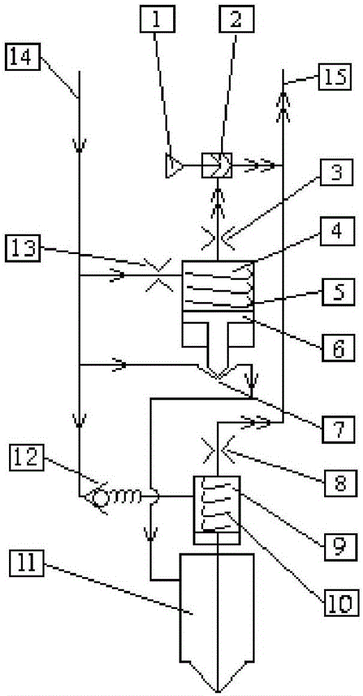
[0030] A new type of electronically controlled fuel injector, such as figure 1 As shown, it includes solenoid valve 1, control chamber valve 2, oil outlet hole 3, control chamber 4, valve 7, throttle hole 8, needle valve chamber 9, fuel injection nozzle 11, check valve 12, oil inlet hole 13, high pressure oil circuit 14, low pressure oil circuit 15;

[0031] The high-pressure oil circuit 14 is divided into three routes:

[0032] One of them enters the control chamber 4 through the oil inlet hole 13 provided between the high pressure oil circuit 14 and the control chamber 4, and then successively passes through the oil outlet hole 3 provided between the control chamber 4 and the low pre...


PUM


Abstract

The present invention provides a novel electrically-controlled oil injector, comprising an electromagnetic valve, a control piston, a control cavity, a one-way valve, a needle valve cavity, an oil nozzle, a high-pressure oil line and a low-pressure oil line; the high-pressure oil line includes three branches, one branch leads to the control cavity through an oil inflow hole and then leads to the low-pressure oil line through an oil outflow hole, another branch leads to the oil nozzle through a lower end valve of the control piston, the remaining branch leads to the oil nozzle needle valve cavity through the one-way valve and then leads to the low-pressure oil line through a throttle hole, and the control piston is never rigidly connected with the oil nozzle. The novel electrically-controlled oil injector has the advantages that pressure of the oil nozzle needle valve cavity is turned into low pressure so that it is possible to reduce opening resistance for an oil nozzle needle valve; the control piston is used to actively control opening and closing of the high-pressure oil line leading to the oil nozzle so that it is possible to reduce closing resistance for the oil nozzle needle valve; the one-way valve is used to increase an oil line leading to the upper end control cavity of the oil nozzle so that it is possible to increase closing power for the oil nozzle needle valve. It is possible to greatly increase the opening and closing speed of the oil nozzle needle valve, thereby increasing oil injection.

Description

technical field [0001] The invention belongs to the technical field of electronically controlled fuel systems, and in particular relates to a novel electronically controlled fuel injector. Background technique [0002] With the development of processing, materials and integrated circuit technology, electronically controlled fuel system technology has become more mature and reliable, and its applicable fields are becoming wider and wider. Represented by the high-pressure common rail fuel system, it is gradually replacing electronically controlled in-line pumps, electronically controlled unit pumps and electronically controlled pump nozzles with its advantages of flexible control of fuel injection rules, independent work of fuel supply and fuel injection, and high fuel injection pressure. and other electronically controlled fuel systems. [0003] However, the core component of the existing high-pressure common rail system - the design idea of ​​the common rail injector has no...

Claims


Application Information

Patent Timeline
Patent Type & Authority Applications(China)
IPC IPC(8): F02M51/06F02M61/16F02M61/10
CPCF02M51/061F02M61/10F02M61/16
Inventor 吴小军奚星徐春龙孙树平顾娇娇王杰高怡李亚芬
Owner CHINA NORTH ENGINE INST TIANJIN
Why Eureka
Try Eureka