Actuating cylinder with mechanical lock arranged inside and locking and unlocking methods of actuating cylinder with mechanical lock arranged inside

A technology for actuators and mechanical locks, applied in the direction of fluid pressure actuation devices, etc., can solve the problems of increased space size, more sealing links, complexity and weight of actuators, etc., to reduce weight and reduce sealing links , the effect of compact structure

Active Publication Date: 2016-11-09
LANDING GEAR ADVANCED MFG
View PDF7 Cites 7 Cited by
  • Summary
  • Abstract
  • Description
  • Claims
  • Application Information

AI Technical Summary

Problems solved by technology

[0002] Common actuators with built-in elastic claw-type mechanical locks cannot realize the normal locking function in the differential state
At the same time, the actuator of this type of lock structure needs to be designed as two independent parts to output the externally loaded piston and the piston to control the unlocking and locking of the lock mechanism, and to realize their functions respectively, so that the complexity and weight of the actuator increase. , the space size increases, and the sealing links increase

Method used


Image

  • Actuating cylinder with mechanical lock arranged inside and locking and unlocking methods of actuating cylinder with mechanical lock arranged inside
  • Actuating cylinder with mechanical lock arranged inside and locking and unlocking methods of actuating cylinder with mechanical lock arranged inside

Examples


Embodiment Construction

[0034] The present invention will be described in detail below with reference to the accompanying drawings and examples. It should be noted that, in the case of no conflict, the embodiments of the present invention and the features in the embodiments can be combined with each other. For the convenience of description, if the words "up", "down", "left" and "right" appear in the following, it only means that the directions of up, down, left and right are consistent with the drawings themselves, and do not limit the structure.

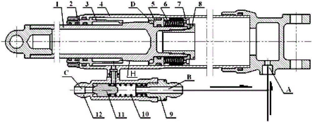
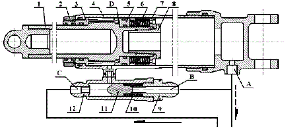
[0035] A differentially controlled built-in mechanical lock actuator such as Figure 1-Figure 2 As shown, it consists of the main body of the actuator and the shuttle valve. The main body of the actuator includes parts such as a piston rod 1, an elastic locking pawl 3, an outer cylinder 4, a traveling piston 5 and a retainer 7. The outer surface of the piston rod 1 is an outer cone surface, and the elastic locking claw 3 locks and unlocks along the oute...


PUM


Abstract

The invention discloses an actuating cylinder with a mechanical lock arranged inside and locking and unlocking methods of the actuating cylinder with the mechanical lock arranged inside. The actuating cylinder with the mechanical lock arranged inside comprises an outer barrel with an inner cavity and a piston rod partially mounted in the outer barrel. The actuating cylinder is structurally characterized in that a moving piston capable of doing reciprocating motion at the end of the piston rod and an elastic lock claw located in a rod cavity are mounted on the piston rod, and a fusiform valve for achieving the differential action of the actuating cylinder is mounted on the outer barrel; and the moving piston is pressed at the end of the piston rod through an elastic element, and a lower position locking groove formed in the outer wall face of the piston rod is arranged between the elastic lock claw and the moving piston and used for cooperating with the elastic lock claw to enable the actuating cylinder to be in a locked state. The elastic lock claw type mechanical lock is arranged at the stretching end of the piston rod of the actuating cylinder and used for locking the piston rod at the full-stretching position. The fusiform valve is mounted on the outer barrel of the actuating cylinder and used for achieving the differential action of the actuating cylinder.

Description

technical field [0001] The invention relates to an actuator with a built-in mechanical lock and methods for locking and unlocking the same, and relates to the technical field of hydraulic actuators. Background technique [0002] Common actuators with built-in elastic claw-type mechanical locks cannot achieve normal locking functions in the differential state. At the same time, the actuator of this type of lock structure needs to be designed as two independent parts to output the externally loaded piston and the piston to control the unlocking and locking of the lock mechanism, and to realize their functions respectively, so that the complexity and weight of the actuator increase. , the space size increases, and the sealing links increase. Contents of the invention [0003] The present invention aims to provide an actuator with a built-in mechanical lock and its locking and unlocking methods. The rod bears a large load through a mechanical lock at the extreme position. ...

Claims


Application Information

Patent Timeline
Patent Type & Authority Applications(China)
IPC IPC(8): F15B15/26
CPCF15B15/26
Inventor 关维邓晓山孟清河慕建全禹新鹏鲁德发张航舟程国良黄立新
Owner LANDING GEAR ADVANCED MFG
Why Eureka
Try Eureka