Hydrodynamic Optimization Method of Hydraulic Valve

An optimization method and hydraulic valve technology, applied in the direction of fluid pressure actuation device, fluid pressure actuation system test, mechanical equipment, etc., can solve the problems of a large number of manual calculation and screening, low design work efficiency, etc.

Active Publication Date: 2017-11-10
HARBIN INST OF TECH
View PDF5 Cites 0 Cited by
  • Summary
  • Abstract
  • Description
  • Claims
  • Application Information

AI Technical Summary

Problems solved by technology

[0003] The purpose of the present invention is to solve the problem that the existing structural optimization design of hydraulic valves requires a large number of manual calculations and screenings to compensate for the influence of hydraulic power, resulting in low design work efficiency, and provides a hydraulic valve hydraulic power optimization method

Method used


Image

  • Hydrodynamic Optimization Method of Hydraulic Valve
  • Hydrodynamic Optimization Method of Hydraulic Valve
  • Hydrodynamic Optimization Method of Hydraulic Valve

Examples


specific Embodiment approach 1

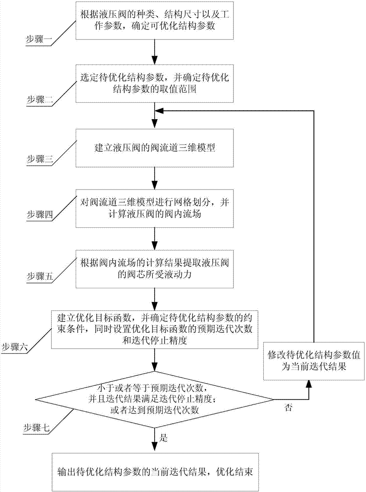
[0019] Specific implementation mode one: the following combination figure 1 Describe this embodiment, the hydraulic power optimization method of hydraulic valve described in this embodiment, it comprises the following steps:

[0020] Step 1: Determine the structural parameters that can be optimized according to the type, structural size and working parameters of the hydraulic valve;

[0021] Step 2: Select the structural parameters to be optimized from the structural parameters that can be optimized, and determine the value range of the structural parameters to be optimized;

[0022] Step 3: According to the current structural size of the hydraulic valve, establish a three-dimensional model of the valve channel of the hydraulic valve;

[0023] Step 4: Mesh the 3D model of the valve channel, and calculate the valve flow field of the hydraulic valve;

[0024] Step 5: Extract the hydraulic force on the spool of the hydraulic valve according to the calculation result of the flow...

specific Embodiment approach 2

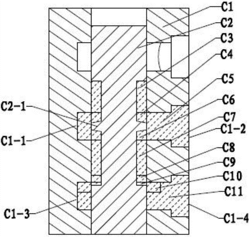
[0028] Specific implementation mode two: the following combination figure 2 Describe this embodiment, this embodiment will further explain Embodiment 1, the hydraulic valve is a slide valve,

[0029] In step 1, the structure of the spool valve includes a valve core and a valve body; three shoulders on the valve core and two sinking grooves on the valve body; the end surface of the lower shoulder of the valve core cooperates with the sinking groove of the valve body to form a throttle valve The middle shoulder of the spool is a hydrodynamic compensating shoulder, which is located in the middle of the second sinking groove on the valve body; the upper shoulder of the valve core seals the valve chamber; the sinking groove on the valve body is connected to the outside through port 1 , the upper sinking groove is connected to the outside through oil port 2;

[0030] The structural dimensions of the spool valve include the diameter of the spool and the opening of the valve port, a...

specific Embodiment approach 3

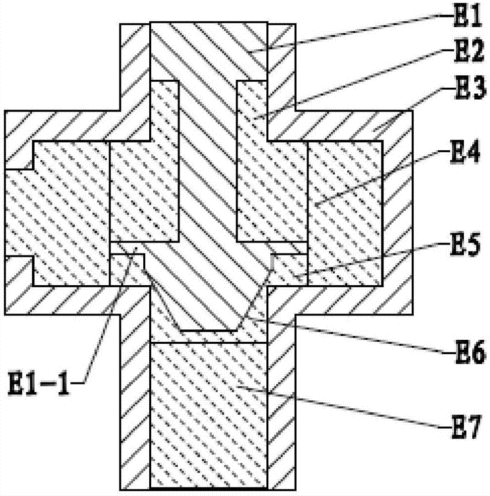
[0052] Specific implementation mode three: the following combination image 3 Describe this embodiment, this embodiment will further explain Embodiment 1, the hydraulic valve is a cone valve,

[0053] In step 1, the structural dimensions of the poppet valve include the diameter of the valve seat hole, the opening of the valve port, the diameter of the valve core guide section, and the diameter of the inlet and outlet; the working parameters of the poppet valve are determined as inlet pressure and outlet pressure, working flow and inlet pressure or working flow rate and outlet pressure; determine the optimized structural parameters of the cone valve as the diameter of the cone valve's hydrodynamic compensation baffle and the distance between the hydraulic compensation baffle and the valve port;

[0054] In step 2, select and determine one or any several of the structural parameters that can be optimized as the structural parameters to be optimized;

[0055] In step 3, divide t...


PUM


Abstract

The invention provides a fluid power optimizing method for a hydraulic valve and belongs to the technical field of structure optimization of hydraulic valves. By the adoption of the fluid power optimizing method for the hydraulic valve, the problem that in the prior art, since a large quantity of manual calculation and screening is needed for structure optimization design of a hydraulic valve to compensate for the influence of fluid power, the designing efficiency is low is solved. The fluid power optimizing method for the hydraulic valve comprises the steps that structure parameters which can be optimized are determined; structure parameters to be optimized are selected, and the value range of the structure parameters to be optimized is determined; a three-dimensional valve flow channel model of the hydraulic valve is established; an intra-valve flow field in the hydraulic valve is calculated; fluid power borne by a valve element of the hydraulic valve is extracted; an optimized objective function is established according to fluid power of the hydraulic valve, constraint conditions of the structure parameters to be optimized are determined, and meanwhile the expected iteration number and iteration stopping precision of the optimized objective function are set; and optimized iteration is conducted on the optimized objective function according to the constraint conditions of the structure parameters to be optimized till the iteration stopping precision or the expected iteration number is achieved, and the optimization process is ended. The fluid power optimizing method is used for structure optimization of the hydraulic valve.

Description

technical field [0001] The invention relates to a hydraulic power optimization method of a hydraulic valve, and belongs to the technical field of hydraulic valve structure optimization. Background technique [0002] Hydraulic power is an important force in the hydraulic valve, which has a great influence on the force balance of the valve, the operation and response characteristics of the valve. Compensating hydraulic forces is a common task in demanding hydraulic valves. Due to the complexity of the law of hydrodynamic action, it is often necessary to carry out a large number of manual calculations and screenings to find suitable parameters to obtain the best compensating hydrodynamic effect. This large amount of calculation work results in low efficiency in the design of hydraulic valves. . Contents of the invention [0003] The purpose of the present invention is to solve the problem that the existing structural optimization design of hydraulic valves requires a large ...

Claims


Application Information

Patent Timeline
Patent Type & Authority Patents(China)
IPC IPC(8): F15B19/00
CPCF15B19/007
Inventor 杨庆俊贾新颖朱冬吕庆军熊庆辉汪俊龙
Owner HARBIN INST OF TECH
Why Eureka
Try Eureka