Circulation self-pollution-discharge self lubricating oil film distribution radial sliding bearing pair

A lubricating oil film and radial sliding technology, applied in sliding contact bearings, rotating bearings, bearings, etc., can solve problems such as carbon deposits, metal debris or other dross, and lubricating oil film damage, so as to maintain the lubricating effect and prolong life. Fault operation time limit, effect of reducing friction loss

Active Publication Date: 2016-11-09
樊勇
View PDF11 Cites 2 Cited by
  • Summary
  • Abstract
  • Description
  • Claims
  • Application Information

AI Technical Summary

Problems solved by technology

[0003] In order to solve and improve the situation that the mating area of ​​the existing radial sliding bearing pair will gradually produce carbon deposits, metal debris or other dross, and the lubricating oil film will be damaged, the present invention provides a device that can discharge the dregs by itself and repair the lubricating oil film. Bearing structure

Method used


Image

  • Circulation self-pollution-discharge self lubricating oil film distribution radial sliding bearing pair
  • Circulation self-pollution-discharge self lubricating oil film distribution radial sliding bearing pair
  • Circulation self-pollution-discharge self lubricating oil film distribution radial sliding bearing pair

Examples


Embodiment 1

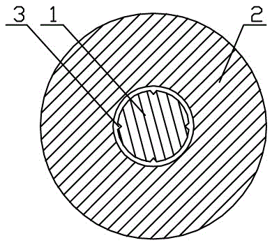
[0024] In this example, if image 3 As shown, a radial sliding bearing pair with circulating self-draining and self-distributing lubricating oil film has a journal 1 and a bearing 2 matching with the journal 1. There are two obliquely arranged grooves 3 evenly arranged around the circumference, and both ends of the grooves 3 protrude from the matching area between the journal 1 and the bearing 2. In terms of the arrangement of the grooves 3, the inclination direction between adjacent grooves 3 unanimous.

Embodiment 2

[0026] In this example, if Figure 4 As shown, a radial sliding bearing pair with circulating self-draining and self-distributing lubricating oil film has a journal 1 and a bearing 2 matching with the journal 1. There are two obliquely arranged grooves 3 in one week, and both ends of the grooves 3 protrude from the matching area between the journal 1 and the bearing 2. In terms of the arrangement of the grooves 3, the two grooves 3 intersect and form a " The X"-shaped cross is arranged on the journal 1, and the other two grooves 3 are symmetrically arranged on the other side of the journal 1.

Embodiment 3

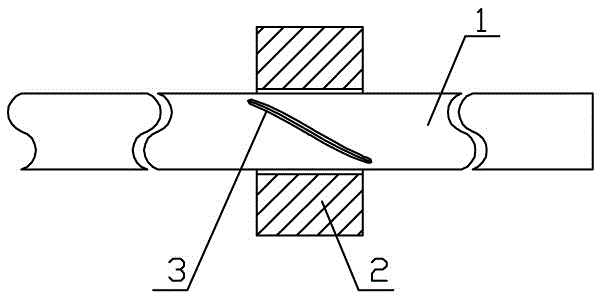
[0028] In this example, if Figure 5 As shown, a radial sliding bearing pair with circulating self-draining and self-distributing lubricating oil film has a journal 1 and a bearing 2 matching with the journal 1. There are two oblique and parallel grooves 3 evenly arranged around the circumference, and the inclination directions of the protruding ends of each groove 3 are the same. One end of the groove 3 protrudes from the matching area between the journal 1 and the bearing 2, and the other end is located In the matching area with the bearing 2 , the inclination direction of the groove 3 is opposite to the rotation direction of the journal 1 .

[0029] In this embodiment, two adjacent grooves can also be arranged obliquely and staggered, see Figure 6 .


PUM


Abstract

The invention relates to the field of mechanical equipment with a rotating pair, in particular to a circulation self-pollution-discharge self lubricating oil film distribution radial sliding bearing pair. At least one groove in inclined arrangement is formed in a region, matched with a bearing, of the surface of a shaft journal; one end of the groove or two ends of the groove extend / extends out of the matched region of the shaft journal and the bearing; the inclination direction of the extending-out end of one end or two ends of the groove is opposite to the rotating direction of the shaft journal. By using a mode of forming the groove in the shaft journal of the bearing pair, accumulated carbon, metal chips and other slag generated in the matched region of the shaft journal and the bearing due to operation are discharged along the groove; the friction surface is cleaned; the abrasion loss of the bearing pair is reduced; meanwhile, a lubrication effect can also be achieved; the fault-free operation time limit of the bearing pair is greatly prolonged; the popularization prospects are good.

Description

technical field [0001] The invention relates to the field of mechanical equipment with rotating pairs, in particular to a radial sliding bearing pair that circulates, discharges sewage, and distributes lubricating oil films. Background technique [0002] The radial sliding bearing pair is one of the common important structures in mechanical shaft transmission equipment. In the actual operation process, especially for a long time, it often occurs that the frictional resistance generated by the bearing pair is too large, resulting in abnormal operation of the bearing. Locking and bearing failure and other problems, the main reasons for such problems are: due to the long-term operation, the mating area between the bearing and the journal will gradually produce carbon deposits, metal debris peeled off from the bearing and the journal or Other dross seriously damages the integrity of the lubricating oil film, so that the working environment of the bearing pair continues to deteri...

Claims


Application Information

Patent Timeline
Patent Type & Authority Applications(China)
IPC IPC(8): F16C17/02F16C33/10
Inventor 樊勇
Owner 樊勇
Why Eureka
Try Eureka