Thread gap elimination device and assembly method thereof

A thread clearance and clearance technology, which is applied to transmissions, transmission parts, belts/chains/gears, etc., can solve the problems of troublesome installation, increased equipment cost, and high manufacturing cost, and achieves simple structure, convenient installation, and elimination of thread clearance. Effect

Inactive Publication Date: 2016-11-09
HUATIAN NANJING ENG & TECH CORP MCC
View PDF7 Cites 2 Cited by
  • Summary
  • Abstract
  • Description
  • Claims
  • Application Information

AI Technical Summary

Problems solved by technology

[0003] Some existing mechanisms for eliminating thread gaps are often complex in structure, contain many parts, high cost, troublesome installation, and increase the cost of equipment

Method used


Image

  • Thread gap elimination device and assembly method thereof

Examples


Embodiment 1

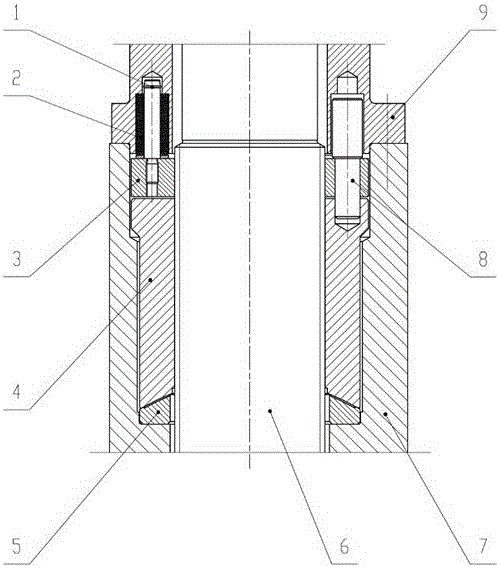
[0022] Such as figure 1 As shown, a thread gap eliminating device of the present invention comprises a transmission screw rod 6, a main nut 4, an auxiliary nut 3, a connecting pin 8, a disc spring pin 1, a disc spring 2, a casing 7, an end cover 9; 9 is fixed on the top of the box body 7 by fasteners, the transmission screw rod 6 passes through the center hole of the box body 7 and the end cover 9, and is set between the inner hole of the box body 7 and the radial direction of the transmission screw rod 9 There are main nut 4 and auxiliary nut 3, the main nut 4 and auxiliary nut 3 are fitted on the external thread of the transmission screw 9 through the internal thread, and there is a certain gap with the inner hole of the box body 7, the auxiliary nut 3 is arranged on the main nut 4, there is a certain gap between the two, the connecting pin 8 connects the end cover 9, the auxiliary nut 3 and the main nut 4, the lower part of the disc spring pin 1 is connected to the auxiliar...

Embodiment 2

[0024] In the above embodiment, the outer diameter of the lower boss of the end cover 9 matches the inner hole of the top of the box body 7 , and its shoulder contacts the upper end surface of the box body 7 .

Embodiment 3

[0026] The inner holes on the lower end surface of the end cover 9 are several stepped blind holes, the depth of the large holes is determined according to the working height of the disc spring 2, the diameter of the large holes is slightly larger than the outer diameter of the disc spring 2, and the upper part of the connecting pin 8 The outer diameter of the large diameter section is slightly smaller than the diameter of the large hole.

[0027] When determining the size of the large hole in the stepped blind hole on the lower end face of the end cover 9, the design sequence is: A. Determine the size of the disc spring 2 according to the force and structural requirements; B. Design the end according to the size of the selected disc spring 2 The size of the large hole section in the inner hole of the lower end surface of the cover 9; C. design the size of the large diameter section on the top of the connecting pin 8 according to the size of the large hole section in the inner ...


PUM


Abstract

The invention discloses a thread gap elimination device and an assembly method thereof. The thread gap elimination device comprises a transmission screw rod, a main nut, an auxiliary nut, a connection pin, a disc spring pin, a disc spring, a box body and an end cover, wherein the end cover is fixed on the box body through a fastener; the transmission screw rod penetrates through from the central holes of the box body and the end cover; the main nut and the auxiliary nut are arranged between the inner hole of the box body and the radial direction of the transmission screw rod; the main nut and the auxiliary nut are matched with an external thread of the transmission screw rod through an internal thread, and form a certain gap with the inner hole of the box body; the auxiliary nut is arranged on the upper part of the main nut, and forms a certain gap with the main nut; the connection pin is connected with the end cover, the auxiliary nut and the main nut; the lower part of the disc spring pin is connected to the auxiliary nut, and the upper part of the disc spring pin is located in the inner hole of the end cover; and the disc spring sleeves outside the disc spring pin, and forms a gap with the inner hole of the end cover. The thread gap elimination device disclosed by the invention is capable of conveniently and reliably eliminating a thread gap. Meanwhile, the thread gap elimination device disclosed by the invention is simple in structure and convenient to install.

Description

technical field [0001] The invention relates to a thread gap eliminating device, in particular to a rolling mill pull rod thread gap eliminating device. At the same time, the present invention also relates to an assembly method of this thread gap eliminating device. Background technique [0002] Screw transmission is widely used in mechanical equipment in various industries. Since there will be a gap of a certain size in the screw transmission mechanism, and the existence of this gap will affect the accuracy and use of the entire equipment, so it is often required in high-precision equipment through other corresponding The mechanism to eliminate the thread gap. [0003] Some existing mechanisms for eliminating thread gaps are often complex in structure, contain many parts, have high cost, and are troublesome to install, which increases the cost of the equipment. Contents of the invention [0004] The problem to be solved by the present invention is to provide a threa...

Claims


Application Information

Patent Timeline
Patent Type & Authority Applications(China)
IPC IPC(8): F16H57/12F16H25/20
CPCF16H57/12F16H25/2003
Inventor 徐志坤谷青林孙保生何家宝
Owner HUATIAN NANJING ENG & TECH CORP MCC
Why Eureka
Try Eureka