Burner cycle detection system based on PLC control unit

A control unit, cycle detection technology, applied in the combustion chamber, combustion method, combustion equipment and other directions, can solve the problems of affecting production, consuming manpower, material and financial resources, and long maintenance time, to achieve convenient maintenance, avoid major accidents, ensure The effect of normal operation

Inactive Publication Date: 2016-11-09
王振涛
View PDF5 Cites 1 Cited by
  • Summary
  • Abstract
  • Description
  • Claims
  • Application Information

AI Technical Summary

Problems solved by technology

However, at present, most of the burners commonly used in China are imported products, and their control systems are not disclosed to the public. Therefore, users cannot understand the working status of the burner in time. Professionals in various industries such as craftsmen conduct on-site investigation step by step. The maintenance time is very long, which consumes a lot of manpower, material resources and financial resources. Moreover, it is often impossible to accurately find out the cause of the failure, which affects production.

Method used


Image

  • Burner cycle detection system based on PLC control unit
  • Burner cycle detection system based on PLC control unit
  • Burner cycle detection system based on PLC control unit

Examples


Embodiment

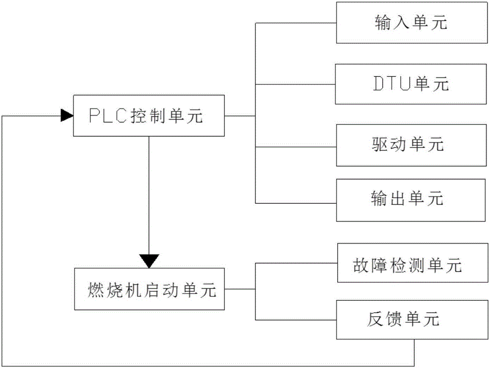
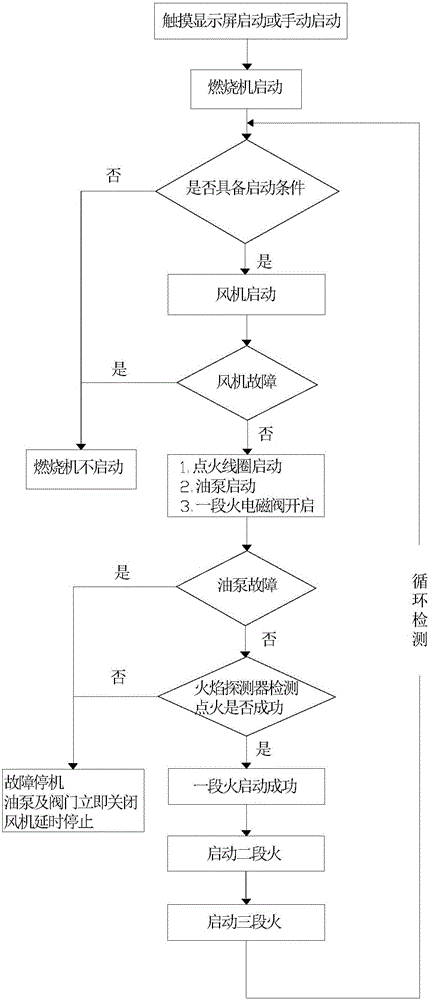
[0024] Examples such as figure 1 , a burner cycle detection system based on a PLC control unit, comprising: a PLC control unit, a burner start unit, the PLC control unit comprising: an input unit, a DTU unit, a drive unit, an output unit, the input unit, the DTU unit, drive unit, and output unit are connected sequentially, and the burner starting unit includes: a fault detection unit and a feedback unit, and the fault detection unit and the feedback unit are connected; the PLC control unit controls the burner starting unit, and the burner The starting unit feeds back the signal to the PLC control unit through the feedback unit.

[0025] Further preferably, the fault detection unit includes a fan fault detection unit, a flame detector detection unit, and an oil pump detection unit, and the fan fault detection unit, the flame detector detection unit, and the oil pump detection unit are set after the burner is started. before the solenoid valve is activated.

[0026] The fan fa...


PUM


Abstract

The invention discloses a burner cycle detection system based on a PLC control unit. The burner cycle detection system comprises the PLC control unit and a burner start unit. The PLC control unit comprises an input unit, a DTU, a drive unit and an output unit, all of which are sequentially connected. The burner start unit comprises a fault detection unit and a feedback unit which are connected. The PLC control unit controls the burner start unit, and the burner start unit feeds signals back to the PLC control unit through the feedback unit. According to the burner cycle detection system, the work state of a burner can be mastered in real time, the work situation of all parts is known, the current ignition step can be judged according to the PLC control unit, the specific fault reason of the earliest action is obtained, the accurate fault reason is provided for maintenance personnel, and targeted maintenance is facilitated; and normal running of the burner is ensured, and major accidents are effectively avoided.

Description

technical field [0001] The invention relates to a cycle detection system, in particular to a burner cycle detection system based on a PLC control unit. Background technique [0002] The burner is a device fueled by light diesel oil, heavy oil, gas, and clean composite fuel. It has the advantages of high efficiency and low emission. Therefore, the burner is widely used in smelting, drying equipment, industrial boilers, spraying, steam, construction, etc. Road machinery, building heating, industrial furnaces and other heating equipment. The commonly used burner refers to the oil-gas burner, which is a device that sends oil-gas fuel and air into the furnace according to the specified ratio, speed and mixing method for timely ignition and efficient and clean combustion. [0003] In order to ensure that the burner can work normally, the user must monitor the working status of the burner in real time to understand the working conditions of each part of the burner, especially the ...

Claims


Application Information

Patent Timeline
Patent Type & Authority Applications(China)
IPC IPC(8): F23M11/04
CPCF23M11/04
Inventor 王振涛王志超
Owner 王振涛
Why Eureka
Try Eureka