Heating furnace waste heat combined cycle recovery system

A technology of combined cycle and recovery system, which is applied in lighting and heating equipment, furnaces, waste heat treatment, etc., can solve the problems of high operating costs and increased investment, and achieve the goals of reducing energy consumption, saving costs, and fully utilizing waste heat Effect

Inactive Publication Date: 2016-11-09
HUATIAN NANJING ENG & TECH CORP MCC
View PDF7 Cites 3 Cited by
  • Summary
  • Abstract
  • Description
  • Claims
  • Application Information

AI Technical Summary

Problems solved by technology

[0002] At present, in order to improve the efficiency of the heating furnace itself and reduce the gas consumption of the heating furnace in the domestic steel rolling mill, the independent vaporization cooling method is generally used to recover the heat of the water beam at the bottom of the furnace. In addition, the waste heat of the flue gas at the tai

Method used


Image

  • Heating furnace waste heat combined cycle recovery system

Examples


Embodiment 1

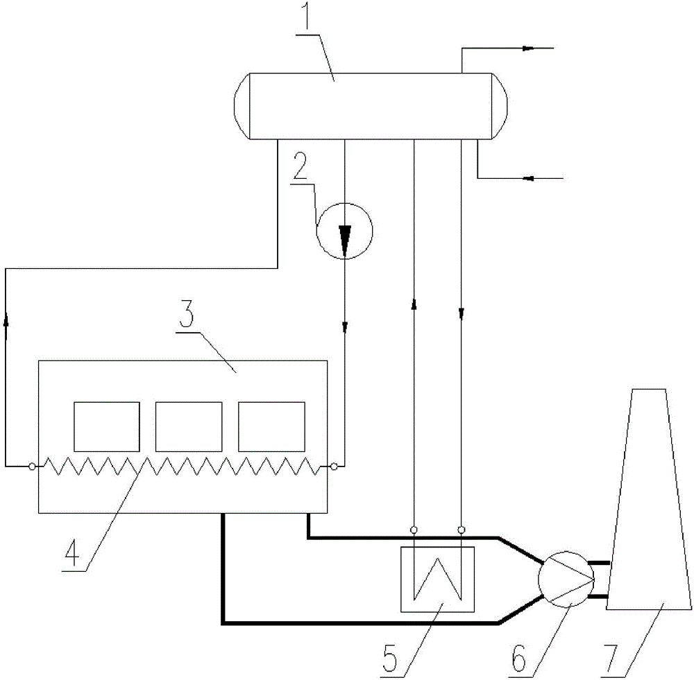
[0017] Such as figure 1 As shown, the waste heat resources recovered by the heating furnace waste heat combined cycle recovery system in this embodiment include two parts: the waste heat of the cooling water beam in the furnace of the heating furnace and the waste heat of the high-temperature flue gas in the tail flue of the heating furnace. A vaporization cooling mechanism 4 is arranged in the hearth of the heating furnace 3 to absorb the waste heat of the water beam at the bottom of the furnace. A flue gas heat exchange mechanism 5 is arranged in the tail flue to absorb the waste heat of the flue gas. The end of the tail flue is connected with the induced draft fan 6, and the induced draft fan 6 is connected with the chimney 7.

[0018] In this embodiment, the heating furnace waste heat combined cycle recovery system includes a vapor-water separation mechanism 1 , a vaporization cooling mechanism 4 , a flue gas heat exchange mechanism 5 and a cycle power mechanism 2 . The ...

Embodiment 2

[0028] On the basis of the above-mentioned embodiments, the vaporization cooling mechanism of the heating furnace waste heat combined cycle recovery system in this embodiment includes a cooling water beam, and one end of the cooling water beam is provided with an inlet of the vaporization cooling mechanism, and the cooling water beam The other end is provided with an outlet of the vaporization cooling mechanism.

[0029] In this embodiment, the water in the steam-water separation mechanism 1 is pumped into the cooling water beam through the circulating power mechanism. On the one hand, the water is used to cool the cooling water beam, and on the other hand, the water absorbs the waste heat in the cooling water beam to produce soda The mixture enters the steam-water separation mechanism 1, which not only ensures the safety of the heating furnace operation, but also utilizes the waste heat.

Embodiment 3

[0031] On the basis of Example 2, the cooling water beam includes an outer tube of the water beam and a core beam coaxially arranged with the outer tube of the water beam in the outer tube of the water beam; one end of the outer tube of the water beam is sealed, and the other One end is sealed and connected with the outer wall of the water beam core tube; one end of the water beam core tube is openly arranged in the water beam outer tube, and the other end is arranged outside the water beam outer tube; the water beam core tube is arranged on The outer end of the water beam outer tube is provided with an inlet of a vaporization cooling mechanism, and the end of the water beam outer tube close to the inlet of the vaporization cooling mechanism is provided with an outlet of a vaporization cooling mechanism.

[0032] In this embodiment, the cooling water of the water girder enters from the middle and flows out from the periphery, so that the water girder can be cooled evenly, and a...


PUM


Abstract

The invention discloses a heating furnace waste heat combined cycle recovery system, and provides a heating furnace waste heat combined cycle recovery system combined with a recovery gasifying and cooling mechanism and tail smoke heat. The system is mainly aimed at solving the problems that many heating furnace waste heat independent recovery devices exist and expenditures are high. The system comprises a gasifying and cooling mechanism arranged in a hearth of a heating furnace, a smoke heat exchange mechanism arranged in a tail flue of the heating furnace and a vapor-water separator, wherein the vapor-water separator comprises a vapor-water container, a natural cycle inlet, a natural cycle outlet, a forced cycle inlet, a forced cycle outlet, a water inlet and a saturated vapor outlet, wherein the natural cycle inlet, the natural cycle outlet, the forced cycle inlet, the forced cycle outlet and the water inlet are formed in the lower portion of the vapor-water container, and the saturated vapor outlet is formed in the upper portion of the vapor-water container. The natural cycle outlet is communicated with the water inlet of the smoke heat exchange mechanism. The natural cycle inlet is communicated with the water outlet of the smoke heat exchange mechanism. The forced cycle outlet is communicated with the inlet of the gasifying and cooling mechanism. The forced cycle inlet is communicated with the outlet of the gasifying and cooling mechanism. The number of devices is small, and running power consumption is low.

Description

technical field [0001] The invention relates to a heating furnace waste heat combined cycle recovery system. Background technique [0002] At present, in order to improve the efficiency of the heating furnace itself and reduce the gas consumption of the heating furnace in the domestic steel rolling mill, the independent vaporization cooling method is generally used to recover the heat of the water beam at the bottom of the furnace. In addition, the waste heat of the flue gas at the tail of the heating furnace is generally used for heating The air, gas, etc. needed for self-combustion have an outlet smoke temperature of about 300-400°C, and then recover this part of heat by using an independent tail flue waste heat boiler. In this waste heat recovery method, the number of equipment is large. The investment amount increases, and the operating cost is also high. Contents of the invention [0003] In view of the above problems, the present invention provides a heating furnace...

Claims


Application Information

Patent Timeline
IPC IPC(8): F27D17/00F22B1/18
CPCF22B1/1892F27D17/004F27D2017/006Y02P10/25
Inventor 王雷王宁山
Owner HUATIAN NANJING ENG & TECH CORP MCC
Why Eureka
Try Eureka