
Dual-lens cutting edge image measuring chamfering machine

A technology of image measurement and chamfering machine, which is applied in the direction of measuring devices, instruments, and optical devices, etc. It can solve the problems of chamfering size, angle and poor consistency, and achieve the effect of accurate alignment

Pending Publication Date: 2016-11-09
上海旌锐精密机械有限公司
View PDF0 Cites 4 Cited by
  • Summary
  • Abstract
  • Description
  • Claims
  • Application Information

AI Technical Summary

Problems solved by technology

Chamfer size, angle and consistency are very poor

Method used


Image

  • Dual-lens cutting edge image measuring chamfering machine
  • Dual-lens cutting edge image measuring chamfering machine
  • Dual-lens cutting edge image measuring chamfering machine

Examples


Embodiment Construction

[0022] The following will clearly and completely describe the technical solutions in the embodiments of the present invention with reference to the accompanying drawings in the embodiments of the present invention. Obviously, the described embodiments are only some, not all, embodiments of the present invention. Based on the embodiments of the present invention, all other embodiments obtained by persons of ordinary skill in the art without making creative efforts belong to the protection scope of the present invention.

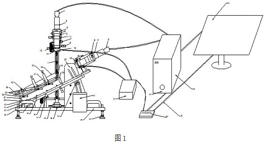
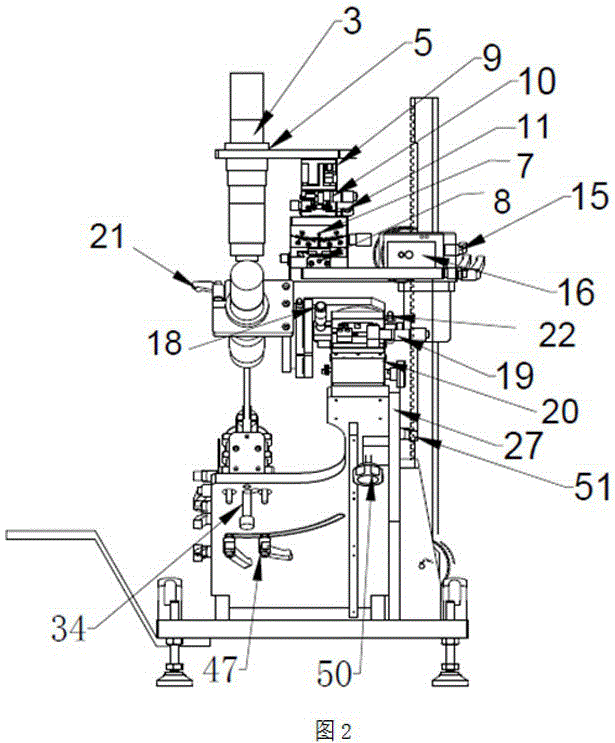
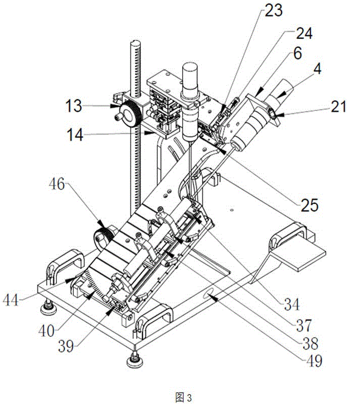
[0023] see Figure 1~3, in an embodiment of the present invention, a double-lens tool edge image measuring chamfering machine includes a vertical camera 1, a side camera 2, a vertical lens 3, a side lens 4, a vertical lens holder 5, a side lens holder 6, a vertical Lens X-axis rotation adjustment mechanism 7, vertical lens Y-axis rotation adjustment mechanism 8, vertical lens X-axis translation adjustment mechanism 9, vertical lens Y-axis translation adjustmen...


PUM


Abstract

The invention discloses a dual-lens cutting edge image measuring chamfering machine comprising a vertical camera, a side camera, a vertical lens, a side lens, a cutting tool, and a slide block. The cutting tool is localized axially by a front positioning block assembly; and positioning and supporting are realized by a V-shaped block assembly, a rear limiting block assembly, an axial positioning screw rod, and a liftable cutter front-end support platform assembly. A positioning block of the front positioning block rotates inwardly at an angle of 90 degrees in a pedestal. A guide rail pedestal rotates at an angle from 0 to 90 degrees in a high-precision arc groove of an inclined plate by using a focal point overlapped point of the vertical lens and the side lens as a rotating axis; and the arc groove uses a cutting cuspidal point localized by the front positioning assembly as a center of circle. A special positioning mechanism is used for positioning at an angle of 0 degree and an angle of 90 degrees; and at any position by rotation, a guide rail pedestal quick-tightening wrench assembly arranged at the lower side of the inclined plate is used for realizing tight locking. With the vertical lens, accurate alignment is realized; and a horizontal lens is used for magnifying the cutting tool to realize cutting tool chamfering, wherein the cutting tool can be magnified by 800 times maximally.

Description

technical field [0001] The invention relates to a tool edge chamfering machine, in particular to a double-lens tool edge image measuring chamfering machine. Background technique [0002] On the main cutting edge of the tool, a narrow plane is ground between the flank face and the rake face of the tool, which can increase the strength of the blade, improve the stress and heat dissipation conditions, and improve the durability of the tool. The technology of tool edge chamfering is a very important issue that has not been paid attention to by people generally. The reason why it is important is that the chamfered tool can effectively improve the strength of the edge, improve the life of the tool and the stability of the cutting process. The cutting edge of the tool after being sharpened by ordinary grinding wheel or diamond grinding wheel does have microscopic notches (ie, tiny chipping and sawing) of different degrees. The former can be observed with the naked eye and a commo...

Claims


Application Information

Patent Timeline
Patent Type & Authority Applications(China)
IPC IPC(8): G01B11/00
CPCG01B11/00
Inventor 钟兴辉
Owner 上海旌锐精密机械有限公司
Learn More