Chamfering device for filter screen frames

A technology of chamfering device and filter screen, applied in positioning devices, feeding devices, automatic control devices, etc., can solve the problems of low chamfering output, difficult to clean sharp iron filings, and the angle of employees running through the sole.

Pending Publication Date: 2021-06-04
岚山环保科技(上海)有限公司
View PDF9 Cites 0 Cited by
  • Summary
  • Abstract
  • Description
  • Claims
  • Application Information

AI Technical Summary

Problems solved by technology

[0003] The purpose of the present invention is to provide a filter screen frame chamfering device for the deficiencies of the prior art, so as to solve the problem that iron filings passing through in the above-mentioned background technology are splashed everywhere, which not only makes cleaning difficult but also causes staff to operate equipment. Sharp iron filings are easy to inlay or penetrate through the soles of the shoes, causing damage to the angle of the employees. At the same time, after the unilateral chamfering of the existing chamfering equipment, the employees need to stop the equipment and turn the workpiece over to chamfer again, which not only causes the chamfering of the whole workpiece The low efficiency also causes the overall workpiece chamfering output to be too low

Method used


Image

  • Chamfering device for filter screen frames
  • Chamfering device for filter screen frames
  • Chamfering device for filter screen frames

Examples


Embodiment Construction

[0029] The following will clearly and completely describe the technical solutions in the embodiments of the present invention with reference to the accompanying drawings in the embodiments of the present invention. Obviously, the described embodiments are only some, not all, embodiments of the present invention. Based on the embodiments of the present invention, all other embodiments obtained by persons of ordinary skill in the art without making creative efforts belong to the protection scope of the present invention.

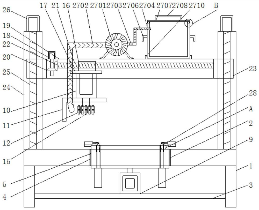
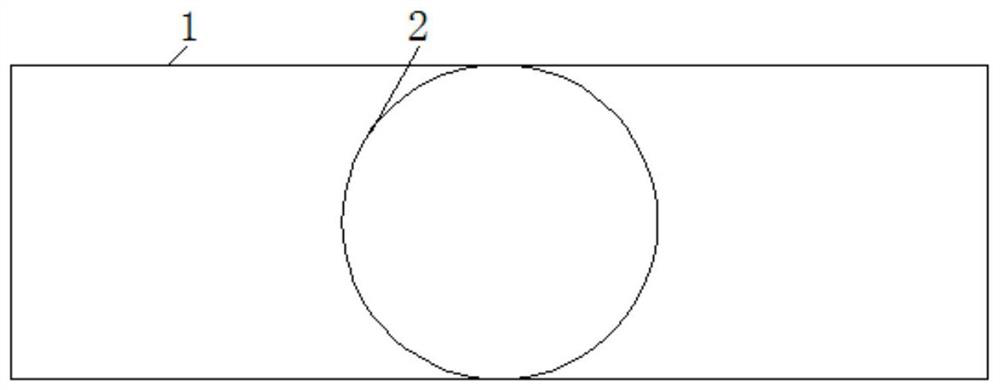
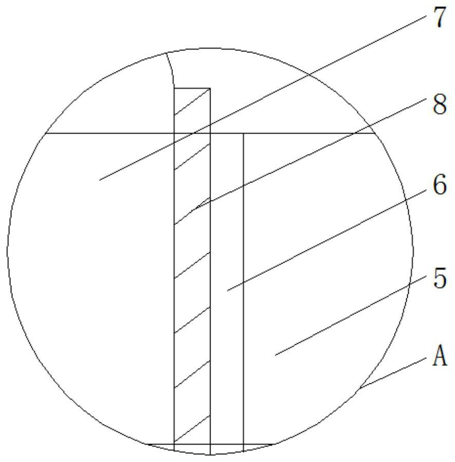
[0030] see Figure 1-7 , the present invention provides a technical solution: a filter screen frame chamfering device, such as figure 2 , image 3 , Figure 4 and Figure 5As shown, the top of the workbench 1 is provided with an installation groove 2, the bottom of the workbench 1 is welded and fixed with a horizontal steel 3, the inside of the installation groove 2 is fixed with a bearing 4, and both sides of the placement plate 5 are provided with a chut...


PUM


Abstract

The invention discloses a chamfering device for filter screen frames. The chamfering device comprises a workbench, a storage plate, a first hydraulic cylinder, a chamfering machine, a chamfering sleeve, chamfering tools, a first screw block, a first rotary motor, a first lead screw, a second lead screw, a chip suction device and an auxiliary rotating mechanism, wherein a mounting groove is formed in the top end of the workbench in a penetrating mode, sliding grooves are formed in the two sides of the storage plate in a penetrating mode, an anti-skid pad is fixedly embedded in the output end of the first hydraulic cylinder, the output end of the chamfering machine penetrates through a baffle, connecting grooves are formed in the periphery of the chamfering sleeve, the chamfering tools are connected into threaded holes in a threaded manner through fixing bolts and are fixed to the periphery of the chamfering sleeve, a connecting plate is fixed to the bottom of the first screw block, a driving bevel gear is fixed to the output end of the first rotary motor, and a driven bevel gear is fixed to the top end of the left side of the first lead screw. The chamfering device for the filter screen frames is provided with the chamfering sleeve, and the chamfering sleeve is connected with the chamfering tools in the threaded mode through the fixing bolts so that the chamfering tools can be replaced conveniently and can also be rapidly assembled and disassembled.

Description

technical field [0001] The invention relates to the technical field of filter screen frames, in particular to a filter screen frame chamfering device. Background technique [0002] Existing air filters are equipped with a frame on the outside, and the filter frame is set according to the overall length and width of the filter, and the manufactured filter frame is in a sharp and right-angled state, which is easy to cause the filter and the filter to be damaged. During the frame installation process, it is easy to cause the installation staff to be injured, so the resulting filter frame needs to be chamfered. Difficulties in cleaning also cause sharp iron filings to be easily inlaid or penetrate through the soles of the employees during the operation of the equipment, causing damage to the angle of the employees. At the same time, after the unilateral chamfering of the existing chamfering equipment is completed, the equipment needs to be stopped by the employees and the workpi...

Claims


Application Information

Patent Timeline
IPC IPC(8): B23D79/00B23Q3/08B23Q7/02B23Q11/00B23Q15/22
CPCB23D79/00B23Q11/0046B23Q7/02B23Q3/082B23Q15/22
Inventor 李浩
Owner 岚山环保科技(上海)有限公司
Why Eureka
Try Eureka