Method for indirectly measuring effective thrust of engine

An effective thrust and engine technology, applied in the field of aerodynamics, can solve problems such as low calculation accuracy

Active Publication Date: 2016-11-09
INHALE HYPERSONIC TECH RES CENT UNIT 63820 OF PLA
View PDF7 Cites 17 Cited by
  • Summary
  • Abstract
  • Description
  • Claims
  • Application Information

AI Technical Summary

Problems solved by technology

The biggest disadvantage of this method is that the resistance of the flow channel when the engine is not working can only be obtained by calculation, and the internal surface of the engine generally has com...

Method used


Image

  • Method for indirectly measuring effective thrust of engine
  • Method for indirectly measuring effective thrust of engine
  • Method for indirectly measuring effective thrust of engine

Examples


Embodiment Construction

[0049] Embodiments of the present invention are described below through specific examples, and those skilled in the art can easily understand other advantages and effects of the present invention from the content disclosed in this specification. The present invention can also be implemented or applied through other different specific implementation modes, and various modifications or changes can be made to the details in this specification based on different viewpoints and applications without departing from the spirit of the present invention.

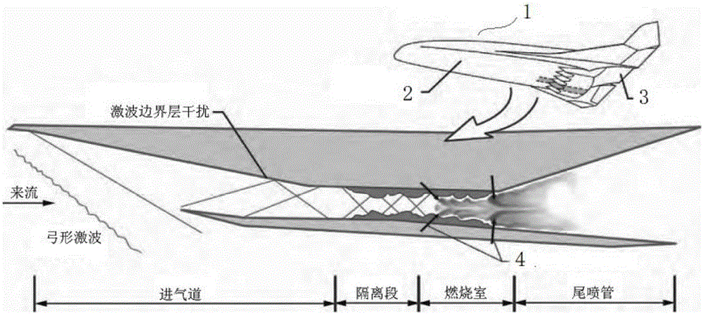
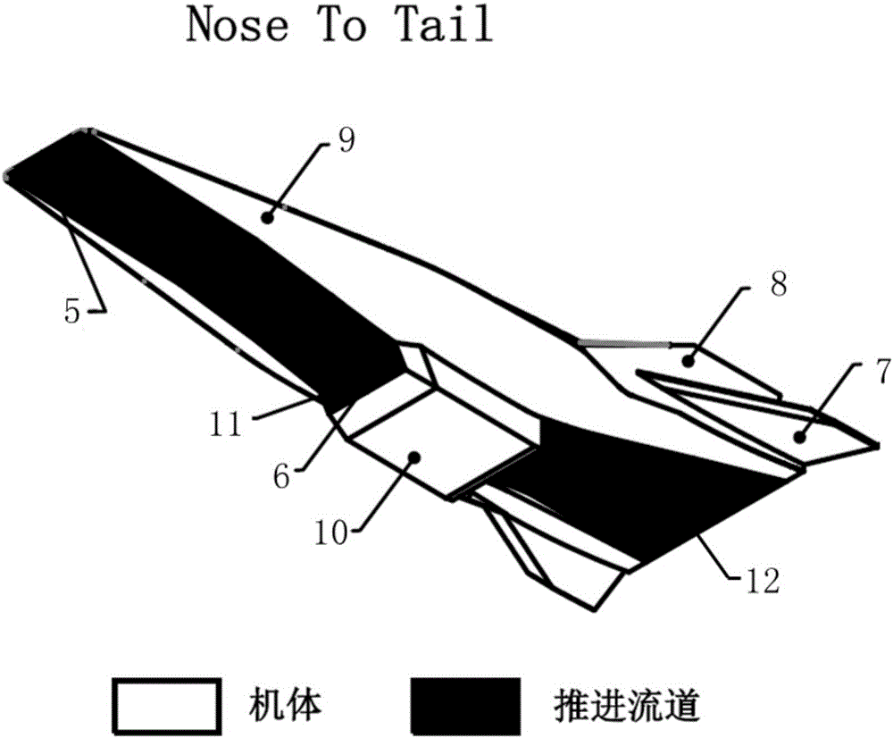
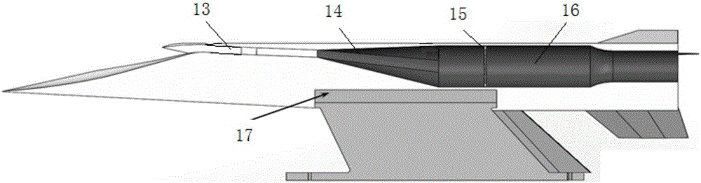
[0050] A method for indirectly measuring the effective thrust of the engine, which is used to measure the effective thrust of the engine of the air-breathing integrated aircraft. The aircraft is a through-flow model, and the thrust-drag characteristic measurement test is carried out in the wind tunnel for the powered aircraft. The wind tunnel The test meets the requirements of the simulation criteria for aerodynamic and engine tests at...


PUM


Abstract

The invention provides a method for indirectly measuring effective thrust of an engine. The method is used for measuring effective thrust of the engine of an aspiration-type integrated aircraft. The aircraft is a flow passage model. An engine-containing aircraft is subjected to thrust-to-drag feature measurement testing in a wind tunnel. Wind tunnel testing meets simulation rules of pneumatic and engine testing at the same time. In the test, an engine ignites to start combustion. A wind tunnel balance measures aircraft total thrust F balance total thrust, and the aircraft total thrust F(balance total thrust) is added with body drag D(external resistance) obtained by calculation or measurement so as to obtain effective thrust of the engine. Calculation of cold-state internal resistance is omitted, the effective thrust of the engine is obtained by adding the total thrust measured by thermal state testing with the body drag outside a flow channel, and the accuracy of measuring the effective thrust of the engine of the aspiration-type integrated aircraft is improved.

Description

technical field [0001] The invention belongs to the technical field of aerodynamics, in particular to a method for indirectly measuring the effective thrust of an engine. Background technique [0002] Existing typical air-breathing integrated aircraft fuselage and engine are highly integrated, such as figure 1 As shown, 1 is the integrated configuration of the body, the front lower surface of the fuselage is the compression surface 2 of the front body of the engine inlet, the rear lower surface of the fuselage is the rear body expansion surface 3 of the engine tail nozzle, and 4 is the fuel injection, There is no clear dividing line between the airframe and the engine. [0003] In order to study the aerodynamic and engine performance of the aircraft, it is necessary to divide the airframe / engine force interface. Using the "noseto tail" division method (Luo Jinling, Zhou Dan, Kang Honglin, et al. A review of research on experimental methods for typical aerodynamic problems ...

Claims


Application Information

Patent Timeline
IPC IPC(8): G01L5/13G01L5/00G01M9/06
CPCG01L5/0038G01L5/133G01M9/06
Inventor 吴颖川贺元元张小庆贺伟王琪高昌吴杰韩奕宇
Owner INHALE HYPERSONIC TECH RES CENT UNIT 63820 OF PLA
Why Eureka
Try Eureka