An automobile longitudinally set composite material plate spring performance testing device

A composite material board and testing device technology, which is applied in the direction of measuring devices, elastic testing, mechanical parts testing, etc., can solve the problem of poor versatility of testing tooling, increase of leaf spring R&D, maintenance, maintenance costs, and the inability of leaf springs to accurately measure boards Problems such as the change value of the center distance of the lifting lug, etc., achieve the effect of simple structure and good versatility

Active Publication Date: 2016-11-09
SAIC MOTOR
View PDF9 Cites 26 Cited by
  • Summary
  • Abstract
  • Description
  • Claims
  • Application Information

AI Technical Summary

Problems solved by technology

Insufficient technology for the stiffness and fatigue test tooling of longitudinal composite leaf springs for automobiles, unable to effectively test the vertical stiffness and fatigue life of longitudinal composite leaf springs;
[0008] 2. The existing leaf spring stiffness and fatigue test device cannot accurately measure the change value of the center distance of the lifting lug of the leaf spring during the test process, and is not suitable for the comprehensive testing of the stiffness of the composite leaf spring;
[0009] 3. Most of the test tools have poor versatility, and can only perform one-to-one measurement for specific types of leaf springs, which increases the cost of research and development, repair and maintenance of leaf springs

Method used


Image

  • An automobile longitudinally set composite material plate spring performance testing device
  • An automobile longitudinally set composite material plate spring performance testing device

Examples


Embodiment 1

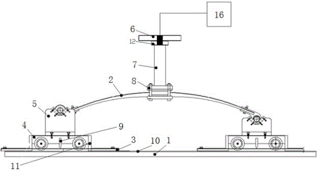
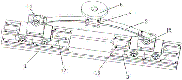
[0030] Such as figure 1 , 2 , a performance test device for longitudinal composite leaf springs of automobiles, comprising a base plate 1 and a plate spring 2 to be tested, the top surface of the base plate 1 is a test reference plane, and a pair of guide rails are symmetrically arranged on both sides of the top surface of the base plate 1 3. A pair of sliders 4 are provided on the guide rail 3, and a support member 5 for positioning the end of the leaf spring 2 to be tested is fixed on the slider 4. A moving pair is formed between the guide rail 3 and the slider 4 and is provided with The matching displacement measuring device can measure the displacement at both ends of the leaf spring through the displacement measuring device;

[0031] The output rod 7 of the load loading system 6 used to pressurize the leaf spring 2 to be tested is connected to the middle part of the leaf spring 2 to be tested by a splint 8, the central axis of the output rod 7 is perpendicular to the tes...


PUM


Abstract

The invention relates to the field of automobile component performance tests and especially relates to an automobile longitudinally set composite material plate spring performance testing device. The automobile longitudinally set composite material plate spring performance testing device comprises a substrate, a to-be-tested plate spring, a pair of guide rails arranged at the two sides of the top surface of the substrate in symmetry and a pair of sliding parts arranged on the guide rails and forming a moving pair with the guide rails. Displacement measurement apparatuses are arranged between the guide rails and the sliding parts in a matched mode. Support parts installed on the sliding parts support the to-be-tested plate spring. An output rod of a load loading system is connected to the central section of the to-be-tested plate spring through a clamping plate. A central axis of the output rod is perpendicular to a test reference surface. According to the invention, through measuring transverse displacement of the plate spring and correcting rigidity of the plate spring by a chord length, the performance of the plate spring of composite materials can be more comprehensively tested; and positioning of the plate spring can be realized through usage of a pair of simple V-shaped support blocks and the deadweight of the plate spring. The testing device is simple in structure, high in universality, and is especially suitable for tests for plate springs of composite materials with different bearing capabilities in different directions.

Description

technical field [0001] The invention relates to the field of performance testing of vehicle components, in particular to a performance testing device for leaf springs. Background technique [0002] Resin-based composite materials have the advantages of high specific strength, large specific elastic energy, corrosion resistance, and designable material properties. These characteristics can not only meet the performance requirements of automotive leaf springs for materials, but also achieve the effect of reducing weight. Therefore, the use of composite material leaf springs in the automotive industry has broad application prospects. [0003] However, the existing composite material leaf springs are processed through the lay-up process during manufacture, which determines the inconsistency of the properties of the leaf springs in all directions, which is very different from the isotropy of ordinary leaf spring materials. Most of the spring test fixtures obtain the stiffness of...

Claims


Application Information

Patent Timeline
Patent Type & Authority Applications(China)
IPC IPC(8): G01M13/00G01M5/00
CPCG01M5/0075G01M13/00
Inventor 陈德玲郭伟石永金周滨雷清陈军
Owner SAIC MOTOR
Why Eureka
Try Eureka