Imaging system of lithium battery pole piece surface defect detection device and using method of imaging system

An imaging system and defect detection technology, which is applied in the field of imaging systems, can solve the problems of secondary damage to pole pieces, cumbersome detection process, and heavy workload, and achieve the effects of improved detection accuracy, simple operation, and high degree of automation

Pending Publication Date: 2016-11-09
WUHAN UNIV OF SCI & TECH
View PDF8 Cites 22 Cited by
  • Summary
  • Abstract
  • Description
  • Claims
  • Application Information

AI Technical Summary

Problems solved by technology

However, this type of detection device has a complex structure, cumbersome detection process, and a large workload, and it is easy to cause secondary damage to the pole piece during the loading and unloading process.

Method used


Image

  • Imaging system of lithium battery pole piece surface defect detection device and using method of imaging system

Examples


Embodiment 1

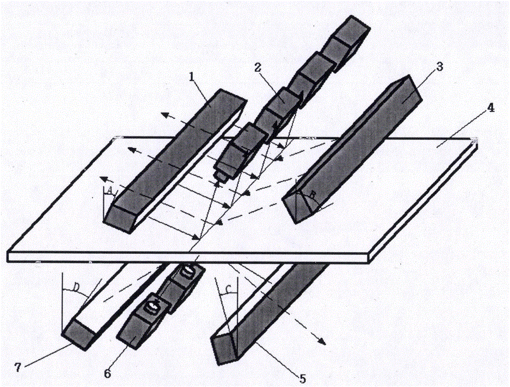
[0023] Embodiment 1: as figure 1 Shown is the imaging system of the lithium battery pole piece surface defect detection device. It can be seen from the figure that the imaging system includes an upper acquisition and detection device placed above the upper surface of the tested pole piece, including a first LED light source 1, a second LED light source 3 and The first line array camera 2; the first LED light source 1 has an inclination angle of 20° relative to the normal line on the plane of the tested pole piece, and its light is reflected by the upper surface of the tested pole piece 4, and the reflected light enters the described pole piece. The main optical axis of the first line array camera lens of the imaging system to form a bright field environment; the first line array camera 2 adjusts the lens to just receive the reflected light of the first LED light source; the second LED light source 3 and the second LED light source Line-array cameras 2 are all above the pole pi...

Embodiment 2

[0034] Embodiment 2: as figure 1Shown is the imaging system of the lithium battery pole piece surface defect detection device. It can be seen from the figure that the imaging system includes an upper acquisition and detection device placed above the upper surface of the tested pole piece, including a first LED light source 1, a second LED light source 3 and The first line array camera 2; the first LED light source 1 has an inclination angle of 30° relative to the normal line on the plane of the tested pole piece, and its light is reflected by the upper surface of the tested pole piece 4, and the reflected light enters the described pole piece. The main optical axis of the first line array camera lens of the imaging system to form a bright field environment; the first line array camera 2 adjusts the lens to just receive the reflected light of the first LED light source; the second LED light source 3 and the second LED light source The line-array cameras 2 are all above the pole...

Embodiment 3

[0045] Embodiment 3: as figure 1 Shown is the imaging system of the lithium battery pole piece surface defect detection device. It can be seen from the figure that the imaging system includes an upper acquisition and detection device placed above the upper surface of the tested pole piece, including a first LED light source 1, a second LED light source 3 and The first line array camera 2; the first LED light source 1 has an inclination angle of 40° relative to the normal line on the plane of the tested pole piece, and its light is reflected by the upper surface of the tested pole piece 4, and the reflected light enters the described pole piece. The main optical axis of the first line array camera lens of the imaging system to form a bright field environment; the first line array camera 2 adjusts the lens to just receive the reflected light of the first LED light source; the second LED light source 3 and the second LED light source The line-array cameras 2 are all above the pol...


PUM


Abstract

The invention relates to an imaging system of a lithium battery pole piece surface defect detection device and a using method of the imaging system. The imaging system comprises a first LED light source, a second LED light source, a third LED light source and a fourth LED light source, and each light source irradiates a same area of a pole piece by a set angle; reflected light generated by the first LED light source and the third LED light source enters a principal optic axis of a line-scan digital camera lens to form a bright field environment, and the rest light sources illuminate to form a dark field environment; a combined mode switching between the bright field environment and the dark field environment is preset; a line-scan digital camera collects images of the surface of the pole piece within a time period in which the preset combined mode is executed completely once. By using the imaging system, two lighting environments are fully utilized to recognize different defects, and defect detection of the surface of the pole piece is completed comprehensively and accurately.

Description

technical field [0001] The disclosure of the present invention relates to defect detection of lithium battery pole pieces, in particular to an imaging system of a lithium battery pole piece surface defect detection device. technical background [0002] Electrodes are important components in lithium batteries. In the pole piece coating process, any link may cause defects such as foil leakage and air bubbles on the surface of the pole piece, which will cause quality problems such as high self-discharge, capacity decay, and short storage time. [0003] At present, most of the manufacturers use manual detection. Since this detection method relies on naked eye recognition, the inspectors are easily affected by subjective factors such as visual fatigue, and there will be errors in missed detection and false detection. Therefore, the detection accuracy is rough and the efficiency is low. In addition, some lithium battery pole piece detection technologies based on machine vision ar...

Claims


Application Information

Patent Timeline
Patent Type & Authority Applications(China)
IPC IPC(8): G01N21/95
CPCG01N21/95
Inventor 刘钊杨雅伦杨柏王兴东刘源泂刘怀广曾镛周三春
Owner WUHAN UNIV OF SCI & TECH
Why Eureka
Try Eureka