
An optical module

A technology of optical modules and lasers, applied in the field of optical modules

Inactive Publication Date: 2016-11-09
HISENSE BROADBAND MULTIMEDIA TECH
View PDF6 Cites 2 Cited by
  • Summary
  • Abstract
  • Description
  • Claims
  • Application Information

AI Technical Summary

Problems solved by technology

[0003] In order to solve the problem that the optical power of the light emitted by the laser is usually greater than the upper limit of the optical power required to be output to the optical fiber, an embodiment of the present invention provides an optical module

Method used


Image

  • An optical module
  • An optical module
  • An optical module

Examples


Embodiment Construction

[0016] In order to make the object, technical solution and advantages of the present invention clearer, the implementation manner of the present invention will be further described in detail below in conjunction with the accompanying drawings.

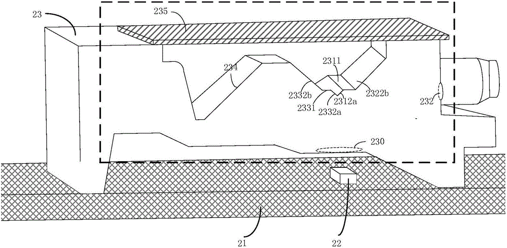
[0017] Before explaining the embodiment of the present invention, the overall structure of the optical module involved in the embodiment of the present invention is firstly introduced, as shown in Figure 2A Shown is a cross-sectional view of a partial structure of the optical module, which includes a circuit board 21 , a laser 22 and a lens module 23 .

[0018] Wherein, the laser 22 and the lens module 23 are both arranged on the circuit board 21 . The laser 22 is set corresponding to the lens module 23, such as Figure 2A The laser 22 shown can be disposed in a cavity formed at the bottom of the lens module 23 . The laser 22 is used as a light source for emitting light perpendicular to the circuit board 21 upwards, entering the fir...


PUM


Abstract

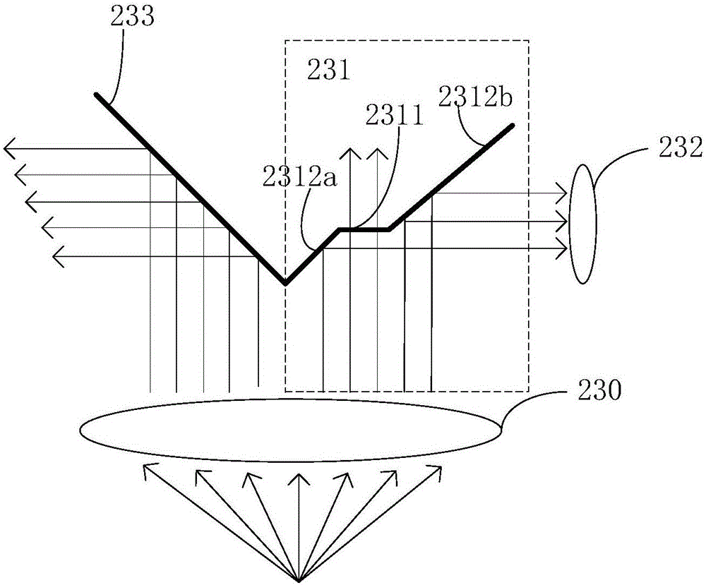
The invention discloses an optical module belonging to the technical field of optical fiber communication. The optical module includes a circuit board, a laser arranged on the circuit board and a lens module group arranged on the circuit board. A first fully reflecting surface of the lens module group is close to a light exit surface of the lens module group. The first fully reflecting surface adopts a step structure. A platform of the step structure is parallel to the circuit board. In the invention, the fully reflecting surface of the lens module group is designed as the step structure so that a part of the light can be directly transmitted through the platform part of the step structure and only part of the light is output to an optical fiber through reflecting, thus realizing the attenuation of the light emitted by the laser and making optical power output to the optical fiber less than an upper limit of the optical power required to be output to the optical fiber.

Description

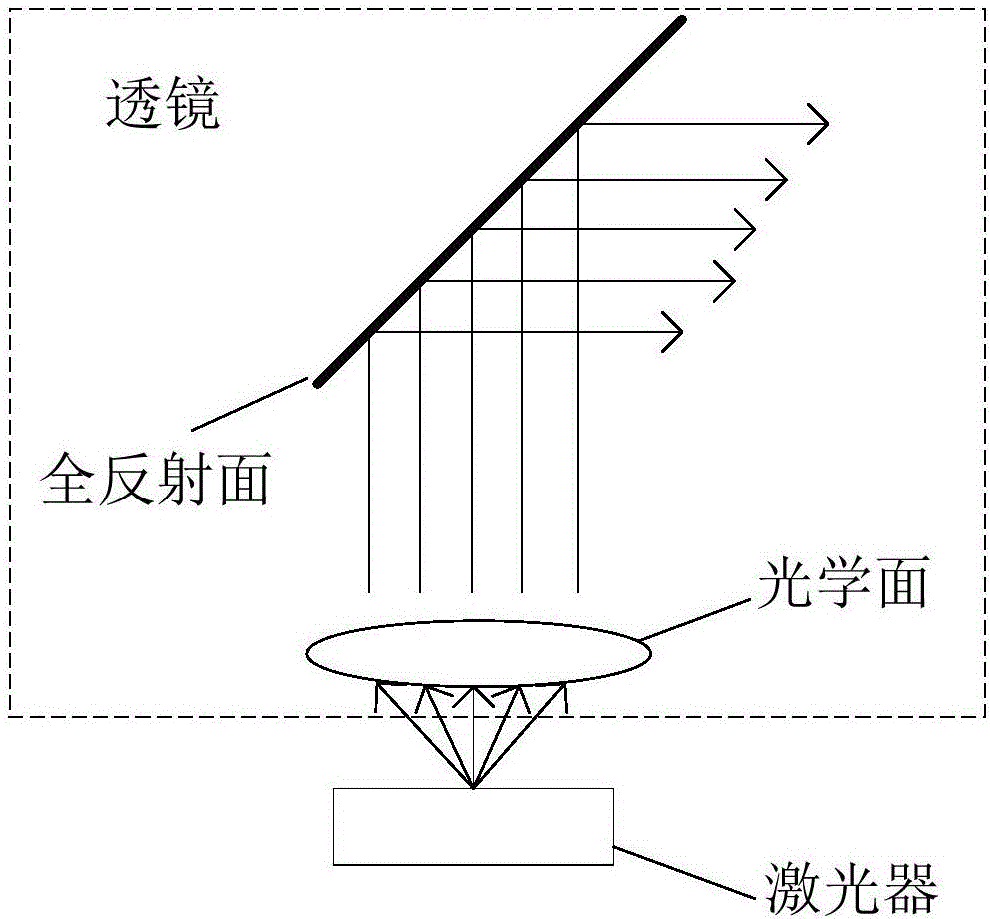
technical field [0001] The invention relates to the technical field of optical fiber communication, in particular to an optical module. Background technique [0002] In the optical fiber communication system, the optical module with the integrated function of optical transceiver is an indispensable device. Usually, such as figure 1 As shown, the optical module that realizes photoelectric conversion in COB (Chip On Board) technology includes a laser and an integral injection-molded lens module. The divergent light emitted by the laser is converted into a parallel Light, the parallel light is incident on the total reflection surface of the lens, the transmission direction of the light is converted through the total reflection surface, and then output to the optical fiber. In practical applications, there is an upper limit requirement for the optical power output to the optical fiber, and the optical power emitted by the laser is usually greater than the upper limit of the re...

Claims


Application Information

Patent Timeline
Patent Type & Authority Applications(China)
IPC IPC(8): G02B6/42
CPCG02B6/4296G02B6/4206
Inventor 黄永亮刘旭霞
Owner HISENSE BROADBAND MULTIMEDIA TECH
Learn More