Apparatus and method for filtering electromagnetic interference

An electromagnetic interference and equipment technology, applied in the direction of transformer/inductor magnetic core, transformer/inductor components, circuits, etc., can solve the problems of equipment 120 degradation, affecting the resonance behavior of coil 103, expensive, etc., and achieve filtering common mode. the effect of interference

Active Publication Date: 2019-07-30
VALEO SYST DE CONTROLE MOTEUR
View PDF4 Cites 0 Cited by
  • Summary
  • Abstract
  • Description
  • Claims
  • Application Information

AI Technical Summary

Problems solved by technology

[0008] Devices 110 and 120 require a certain number of additional components to attenuate the resonance observed at the cutoff frequency of the LC filter of device 100, which is expensive and may create other disadvantages
For example, in the case of the filter 120, each additional branch 121 placed in parallel with the coil 103 may generate stray capacitance affecting the resonant behavior of the coil 103, thereby degrading the behavior of the device 120

Method used


Image

  • Apparatus and method for filtering electromagnetic interference
  • Apparatus and method for filtering electromagnetic interference
  • Apparatus and method for filtering electromagnetic interference

Examples


Embodiment Construction

[0042] At the level of the device 1, the wire comprises three electrical conductors 5, each extending between a first end 7 and a second end 8, said ends 7 and 8 forming a first end for the device 1. end 7 and second end 8.

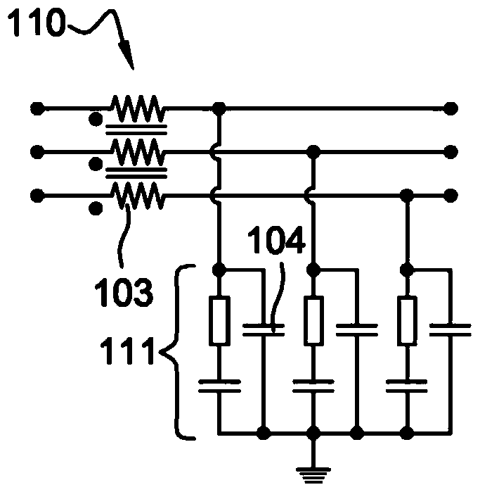
[0043]Between ends 7 and 8 , each electrical conductor 5 comprises a first coil 10 . The first coils 10 each include the same first number of turns, and they wind around a common magnetic core, being magnetically coupled together. These first coils 10 thus form a common mode inductance.

[0044] The device 1 also comprises a capacitor 13 located between each second end 8 of the conductor and the third common terminal 15 of the device 1 . Such as Figure 4 , where this third terminal 15 is linked to ground.

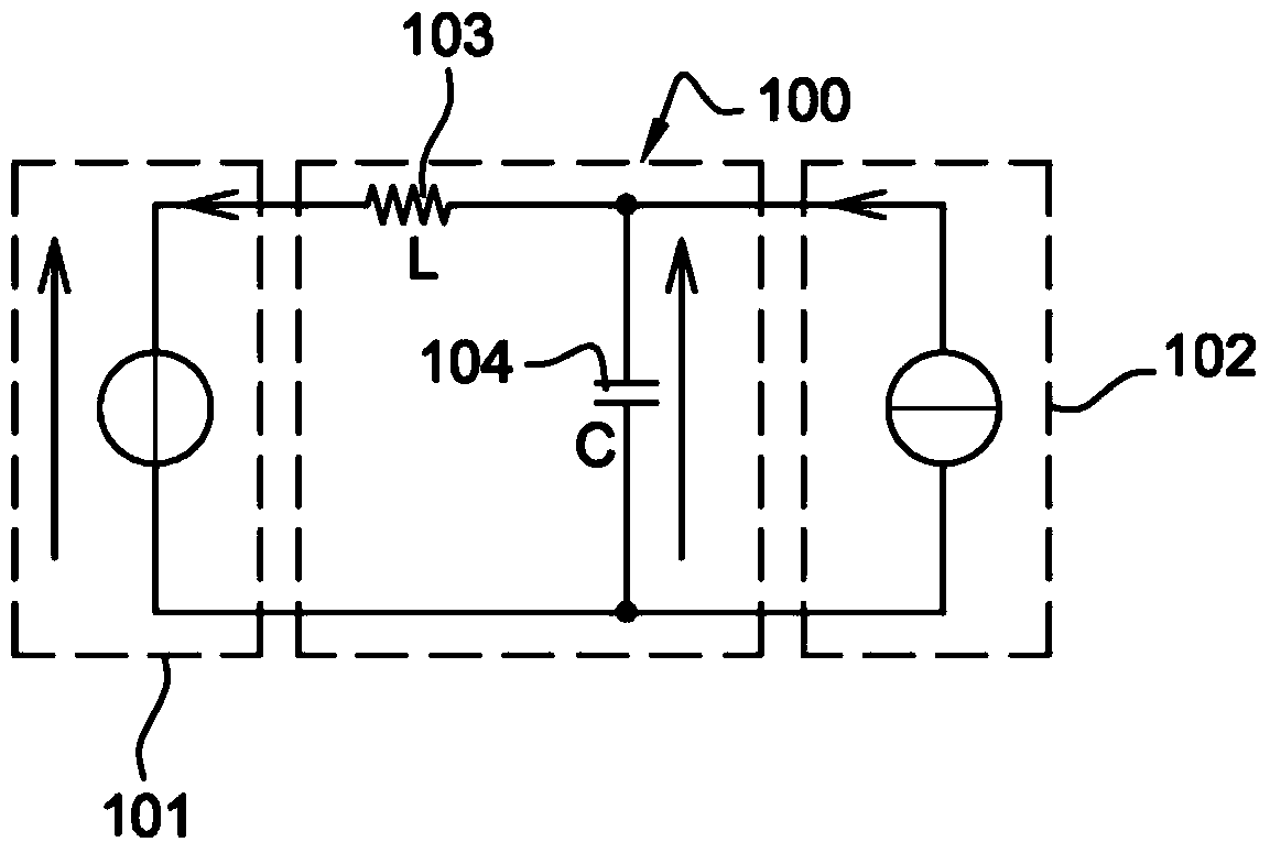
[0045] For each phase of the electrical signal conveyed through the wires, the first coil 10 and the capacitor 13 form a figure 1 The described filter 100 is an LC filter.

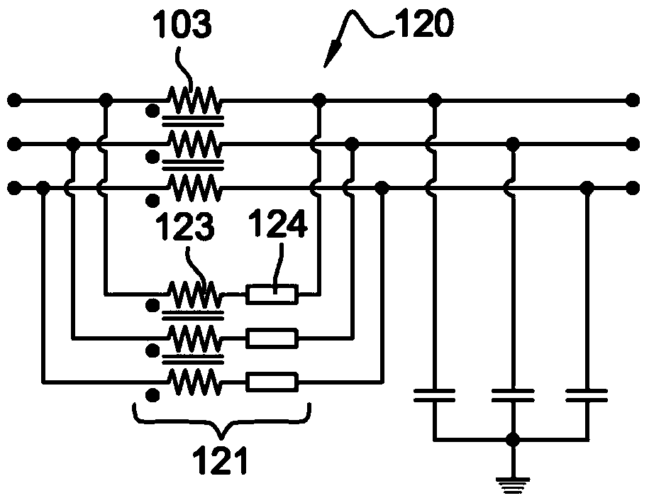
[0046] as in Figure 4 As can be seen in , the device 1 also comprise...


PUM


Abstract

A device (1) for filtering electromagnetic interference, comprising: - a plurality of electrical conductors (5) arranged in parallel, each conductor (5) comprising a first end (7) and a second end (7) placed on the conductor (5) The first coil (10) between the two ends (8), the first coil (10) is magnetically coupled together and presents one and the same first number of turns, the first end of the conductor (5) ( 7) and the second terminal (8) respectively define a first terminal (7) and a second terminal (8) with respect to the device, - a plurality of capacitors (13), each capacitor (13) is placed on the electrical conductor (5) between the second end (8) of the device and the third terminal (15) of the device, and an additional circuit (20) comprising a second coil (21) magnetically coupled to the first coil (10) and exhibiting a second number of turns , the circuit (20) further includes an additional coil (23).

Description

technical field [0001] The present invention relates to the filtering of electromagnetic interference (also referred to simply as EMI). For example, such electromagnetic disturbances occur at frequencies above 1 kHz, such frequencies corresponding eg to the switching frequency of solid-state converters. Such EMI disturbances are related to common-mode currents and differential-mode currents. Background technique [0002] For example, the invention is suitable for filtering electromagnetic interference in the exchange of electrical energy that occurs between the grid and an electrical energy storage unit, notably, where the electrical energy storage unit is installed on an electric or hybrid vehicle. For example, an electrical energy storage unit is used to power an electric motor used to drive a vehicle. [0003] It is known practice to use passive filters to reduce such electromagnetic interference. exist Figures 1 to 3 Numerous examples of such passive filters placed i...

Claims


Application Information

Patent Timeline
Patent Type & Authority Patents(China)
IPC IPC(8): H02M1/12H03H7/42H03H7/09
CPCH02M1/126H03H7/09H03H7/427H02M1/123H01F27/24H01F27/2823H02M1/44H03H1/0007H03H7/0115H03H7/06
Inventor D.奥斯瓦尔德
Owner VALEO SYST DE CONTROLE MOTEUR
Why Eureka
Try Eureka