A light splitting coupling device and method

A coupling device and light-splitting technology, applied in the field of optical coupling, can solve the problems of large volume of the coupling device and low signal detection accuracy of the detector, and achieve the effects of reducing the volume, improving the accuracy and solving the time delay.

Inactive Publication Date: 2018-12-21
INST OF FLUID PHYSICS CHINA ACAD OF ENG PHYSICS
View PDF3 Cites 0 Cited by
  • Summary
  • Abstract
  • Description
  • Claims
  • Application Information

AI Technical Summary

Problems solved by technology

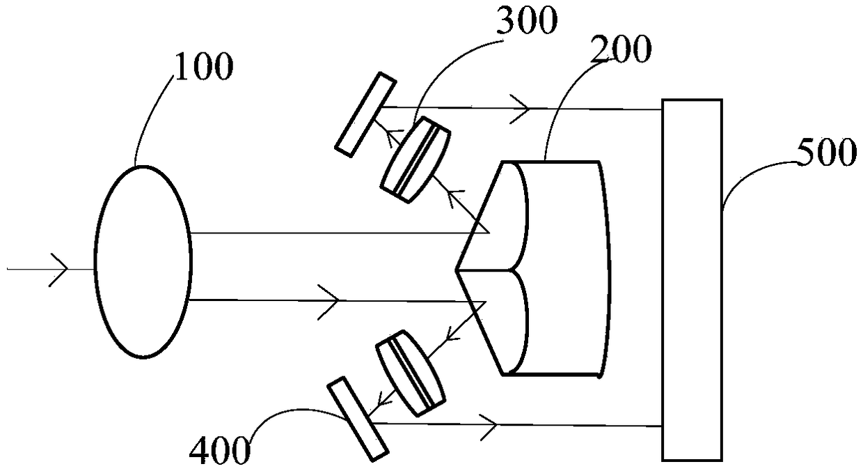
[0002] At present, the coupling device used in the field of ultra-high temperature detection technology, when coupling the target light, uses a plurality of filters arranged in sequence to filter out the wavelength of the required radiation spectrum step by step, and then enters the detector. The time required for the optical signal to reach the detector is inconsistent. The optical signal extracted by the filter arranged in the front reaches the detector first, and the optical signal extracted by the filter arranged in the rear reaches the detector last. Therefore, the optical signal obtained by the detector Spectral signals are not sent at the same time, but there is a certain delay, which leads to low signal detection accuracy of the detector
In addition, the method of step-by-step screening with multiple filters also leads to a larger volume of the coupling device

Method used


Image

  • A light splitting coupling device and method
  • A light splitting coupling device and method
  • A light splitting coupling device and method

Examples


Embodiment Construction

[0031] The following will clearly and completely describe the technical solutions in the embodiments of the present invention with reference to the accompanying drawings in the embodiments of the present invention. Obviously, the described embodiments are only some, not all, embodiments of the present invention. The components of the embodiments of the invention generally described and illustrated in the figures herein may be arranged and designed in a variety of different configurations. Accordingly, the following detailed description of the embodiments of the invention provided in the accompanying drawings is not intended to limit the scope of the claimed invention, but merely represents selected embodiments of the invention. Based on the embodiments of the present invention, all other embodiments obtained by those skilled in the art without making creative efforts belong to the protection scope of the present invention.

[0032] It should be noted that like numerals and let...


PUM


Abstract

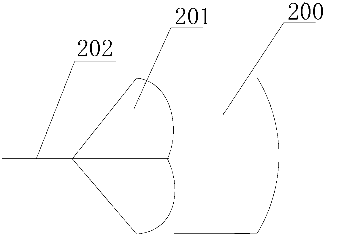
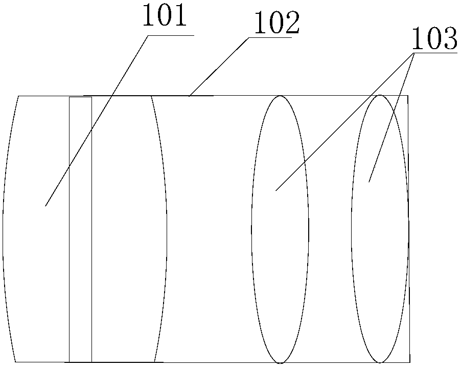
The invention relates to the technical field of optical coupling, and particularly relates to a spectroscopic coupling device and method. The spectroscopic coupling device comprises a first lens group, a splitting pyramid, at least two filters and an image intensifier. The splitting pyramid comprises at least two reflecting surfaces. Each reflecting surface is provided with a reflecting film. The first lens group is used for collecting and collimating target light. Light outputted by the first lens group is divided into at least two beans of light by at least two reflecting surfaces of the splitting pyramid. Each beam of light in at least two beans of light is totally reflected to at least one filter in at least two filters. Light output by at least two filters is coupled to the image intensifier. According to the spectroscopic coupling device and method, the splitting pyramid can divide a spectral signal emitted by a target into at least two beams of light; at least two beams of light can reach a detector at the same time through the filters; the accuracy of signal measurement is greatly improved; and the size of the device is small.

Description

technical field [0001] The present invention relates to the field of optical coupling technology, in particular to an optical coupling device and method. Background technique [0002] At present, the coupling device used in the field of ultra-high temperature detection technology, when coupling the target light, uses a plurality of filters arranged in sequence to filter out the required radiation spectrum wavelength step by step, and then enters the detector. The time required for the optical signal to reach the detector is inconsistent. The optical signal extracted by the filter arranged in the front reaches the detector first, and the optical signal extracted by the filter arranged in the rear reaches the detector last. Therefore, the optical signal obtained by the detector Spectral signals are not sent at the same time, but there is a certain delay, which leads to low signal detection accuracy of the detector. In addition, the step-by-step screening method of multiple op...

Claims


Application Information

Patent Timeline
Patent Type & Authority Patents(China)
IPC IPC(8): G02B27/14
CPCG02B27/14
Inventor 王荣波周维军陈光华罗振雄蒙建华何莉华田建华
Owner INST OF FLUID PHYSICS CHINA ACAD OF ENG PHYSICS
Why Eureka
Try Eureka