Topological optimization method of load-controllable transfer structure

A topology optimization and load technology, applied in design optimization/simulation, special data processing applications, instruments, etc., can solve problems such as poor practicability and achieve the effect of high flexibility

Active Publication Date: 2016-11-09
NORTHWESTERN POLYTECHNICAL UNIV
View PDF2 Cites 9 Cited by
  • Summary
  • Abstract
  • Description
  • Claims
  • Application Information

AI Technical Summary

Problems solved by technology

[0004] In order to overcome the shortcomings of poor practicability of existing topology optimization metho

Method used


Image

  • Topological optimization method of load-controllable transfer structure
  • Topological optimization method of load-controllable transfer structure
  • Topological optimization method of load-controllable transfer structure

Examples


Embodiment Construction

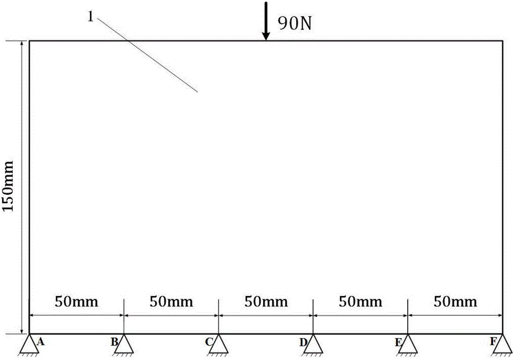
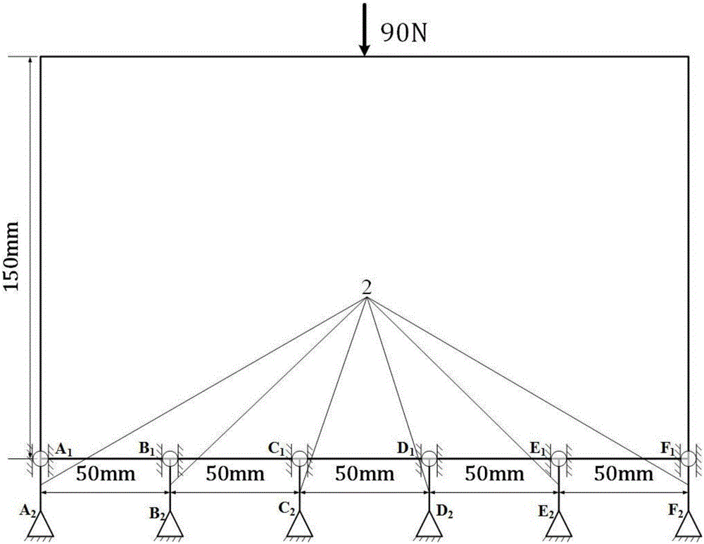
[0024] refer to Figure 1-4 . The specific steps of the topology optimization method of the load controllable transfer structure of the present invention are as follows:

[0025] The present invention is described by taking a rectangular flat plate as an example. The size of the topological design domain 1 of the two-dimensional connection structure is 250mm×150mm×1mm, Young’s modulus E=2.1×10 5 Mpa, Poisson's ratio μ=0.3. The concentrated force of F=90N acts on the midpoint of the top of the structure as shown in the figure. The upper rectangular plate is the design domain of the topology design area, and the bottom is evenly spaced with six support positions. The support position A is required. 2 and F 2 、B 2 and E 2 、C 2 and D 2 The magnitudes of the vertical support reaction forces provided for the system are 20N, 15N, and 10N respectively. Auxiliary bar unit 2 at the supporting position is denoted as A 1 A 2 to F 1 f 2 , in order to realize the controllable t...


PUM


Abstract

The invention discloses a topological optimization method of a load-controllable transfer structure and aims at solving the technical problem of poor practicability of an existing topological optimization method. According to the technical scheme, a topological optimization model is established firstly, a topological design area is defined as Omega1, rod units jointly form an area Omega2; secondly, rod unit displacement constraint values ui are calculated according to displacement response uOmega of a finite element analysis and computation structure; then, the sensitivity of node displacement to the pseudo density Etae of units in the design area is calculated; finally, displacement constraints of upper-portion nodes of the rod units are introduced in the optimization process, optimization is performed according to the obtained sensitivity, and optimization iteration is performed to obtain results. The topological optimization method converts constraint node load into constraint node displacement by adding auxiliary rod units, achieves controllable load transfer through the constraint node displacement, facilitates optimization constraint modeling and rapid model change and has higher flexibility, universality and accuracy.

Description

technical field [0001] The invention relates to a topology optimization method, in particular to a topology optimization method for a load controllable transfer structure. Background technique [0002] In the process of aircraft structure design, it should be ensured that the structure has sufficient strength and rigidity under various specified load states, and each load-bearing structure is coordinated with each other to ensure that the load is reasonably transmitted within the structure. Taking the aircraft wing as an example, the wing girder needs to pass the aerodynamic load to the fuselage reasonably through the connection structure with the fuselage during flight, so as to ensure that the aircraft completes various air movements. Therefore, in the structural design of aircraft, it is of great significance to rationally design the configuration form of the load-bearing structure, match the bearing capacity of the structure with its structural form, and realize the cont...

Claims


Application Information

Patent Timeline
IPC IPC(8): G06F17/50
CPCG06F30/15G06F30/23G06F2111/04
Inventor 朱继宏曹吟锋郭文杰李昱张卫红
Owner NORTHWESTERN POLYTECHNICAL UNIV
Why Eureka
Try Eureka