Drive circuit of piezoelectric ceramics atomization plate
A driving circuit, piezoelectric ceramic technology, applied in the direction of high-efficiency power electronic conversion, electrical components, adjusting electrical variables, etc. The problem of large signal difference, etc., achieves the effect of good atomization effect, flexible use and high controllability
- Summary
- Abstract
- Description
- Claims
- Application Information
AI Technical Summary
Problems solved by technology
Method used
Image
Examples
Embodiment 1
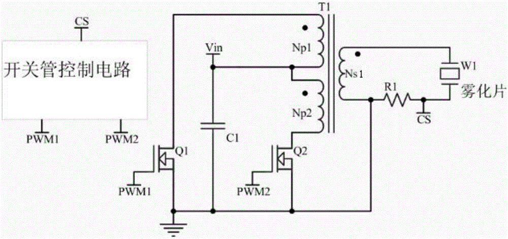
[0029] In this example, if figure 1 As shown, the high-frequency pulse generating circuit includes a power supply output terminal (Vin), a transformer (T), a first switching tube (Q1), a second switching tube (Q2) and a switching tube control circuit, and the transformer includes a matching first primary Side winding (Np1), the second primary winding (Np2), the first secondary winding, the first secondary winding (Ns1) and the iron core, the first secondary winding is connected in parallel with the atomizing sheet, the first primary winding and the second A switching tube is connected in series and parallel to the output end of the power supply, and the second primary winding and the second switching tube are connected in series and parallel to the output end of the power supply. The switching tube control circuit outputs the first control signal and the second control signal, and the first control signal input to the first switch tube, and the second control signal is input t...
Embodiment 2
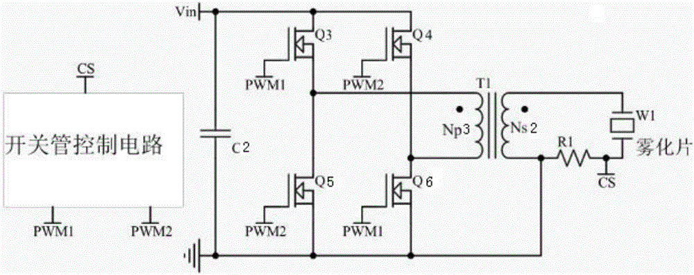
[0038] The difference between this embodiment and embodiment 1 is that, as figure 2 As mentioned above, the high-frequency pulse generating circuit includes a power supply output terminal (Vin), a transformer (T), a third switching tube (Q3), a fourth switching tube (Q4), a fifth switching tube (Q5), a sixth switching tube ( Q6) and the switching tube control circuit, the transformer includes the matching third primary winding (Np3), the second secondary winding (Ns2) and the iron core, the third switching tube and the fifth switching tube are connected in parallel and both ends are respectively connected to The input end of the power supply and one end of the third primary winding, the fourth switching tube and the sixth switching tube are connected in parallel, and the two ends are respectively connected to the output end of the power supply and the other end of the third primary winding, and the other end of the third primary winding is connected to There is one end of the...
Embodiment 3
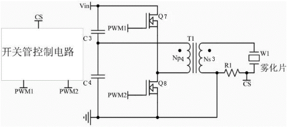
[0043] The difference between this embodiment and embodiment 1 is that, as image 3 As shown, the high-frequency pulse generating circuit includes a power supply output terminal (Vin), a transformer (T), a seventh switching tube (Q7), an eighth switching tube (Q8) and a switching tube control circuit, and the transformer includes a matching fourth principle The side winding (Np4), the third secondary winding (Ns3) and the iron core, the third secondary winding is connected in parallel with the atomizing sheet, one end of the fourth primary winding is connected in series with the seventh switching tube and then connected in parallel to the output end of the power supply, and the fourth One end of the primary winding is connected in series with the eighth switch tube and then connected in parallel to the output terminal of the power supply, the switch tube control circuit outputs the first control signal and the second control signal, the first control signal is input to the seve...
PUM
 Abstract
Description
Claims
Application Information
 - R&D
- Intellectual Property
- Life Sciences
- Materials
- Tech Scout
- Unparalleled Data Quality
- Higher Quality Content
- 60% Fewer Hallucinations
Browse by: Latest US Patents, China's latest patents, Technical Efficacy Thesaurus, Application Domain, Technology Topic, Popular Technical Reports.
© 2025 PatSnap. All rights reserved.Legal|Privacy policy|Modern Slavery Act Transparency Statement|Sitemap|About US| Contact US: help@patsnap.com


