Signal processing circuit for optical disc drivers and the related method

a technology of optical discs and signal processing circuits, applied in the field of signal processing circuits, can solve the problems of inability to suitably process the reflected signal of a loaded optical disc, which is then read by an optical pickup head, and cannot be properly manipulated in electrical form, so as to prevent the reduction of the bandwidth of the related signal, the effect of reducing the operating power consumption

Active Publication Date: 2005-07-21
VIA TECH INC
View PDF3 Cites 8 Cited by
  • Summary
  • Abstract
  • Description
  • Claims
  • Application Information

AI Technical Summary

Benefits of technology

[0009] It is therefore a primary object of the claimed invention to provide a signal processing circuit for alternately selecting an attenuator or a gain controllable amplifier to adjust the amplitude of related input signal so as to overcome the above-mentioned problems. The signal processing circuit can decrease the operating power consumption and prevent related signal bandwidth from decreasing.
[0011] In another embodiment, a signal processing method is disclosed for enabling one of the attenuator and gain controllable amplifier to adjust the signal amplitude of an input signal at a time. The signal processing method includes attenuating the input signal and generating a corresponding attenuated output signal, wherein the attenuator and the gain controllable amplifier are coupled in parallel; and slicing the waveform of the attenuated output signal to generate a digital output signal. The disclosed method further includes a step of amplifying the input signal and generating a corresponding amplified output signal when the attenuated output signal is less than a first threshold. In the embodiment, the step of attenuating the input signal is halted when the amplifying step is performed, while the amplifying step is halted when the attenuating step is performed so as to reduce power consumption when converting signal format of the input signal.

Problems solved by technology

Basically, information in electrical form cannot be properly manipulated until an electrical circuit adjusts this information into digital form.
For example, a reflected signal from a loaded optical disc, which is then read by an optical pickup head, cannot be suitably processed if its format is not converted into a digital format.

Method used


Image

  • Signal processing circuit for optical disc drivers and the related method
  • Signal processing circuit for optical disc drivers and the related method
  • Signal processing circuit for optical disc drivers and the related method

Examples


Embodiment Construction

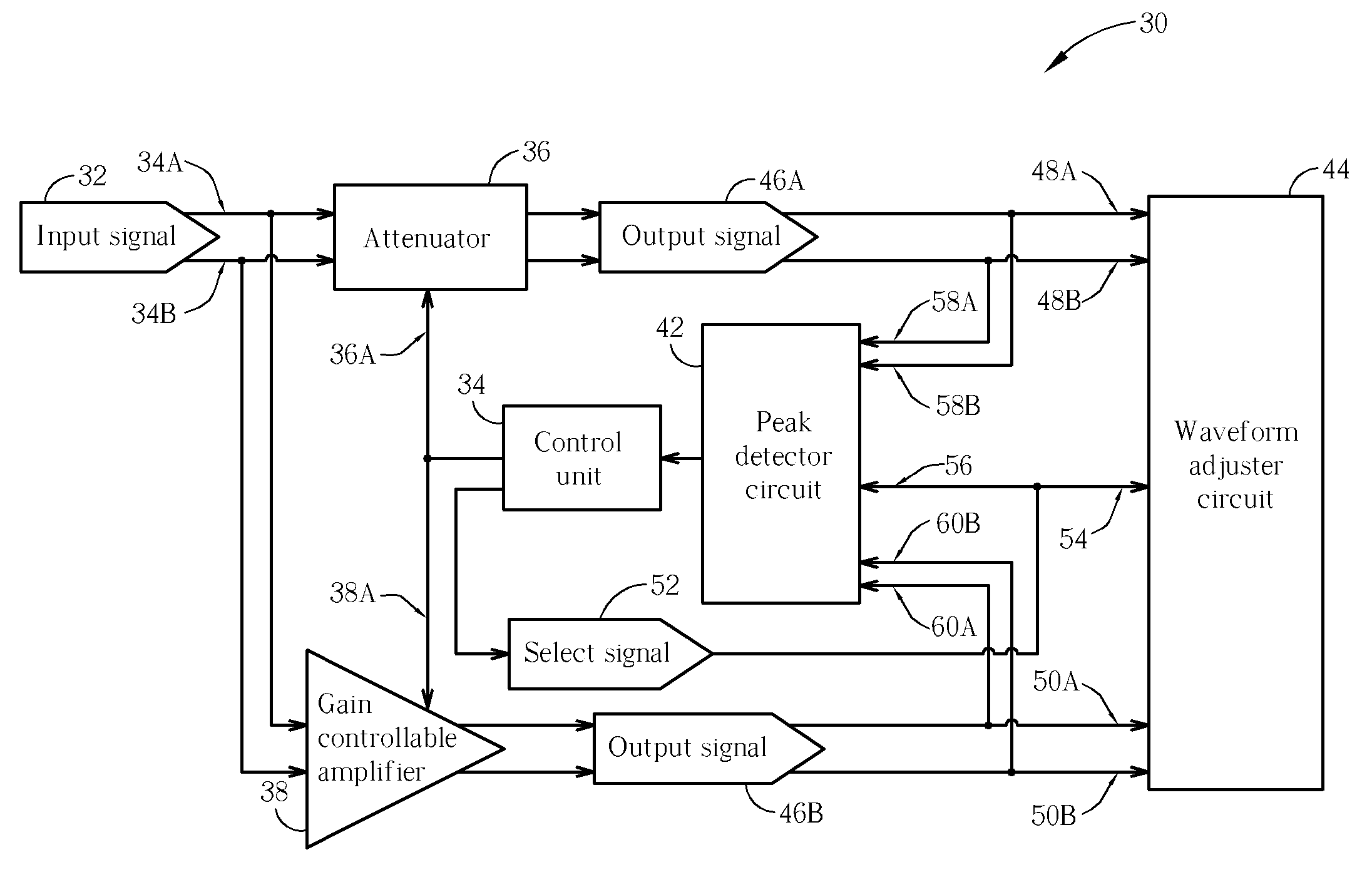
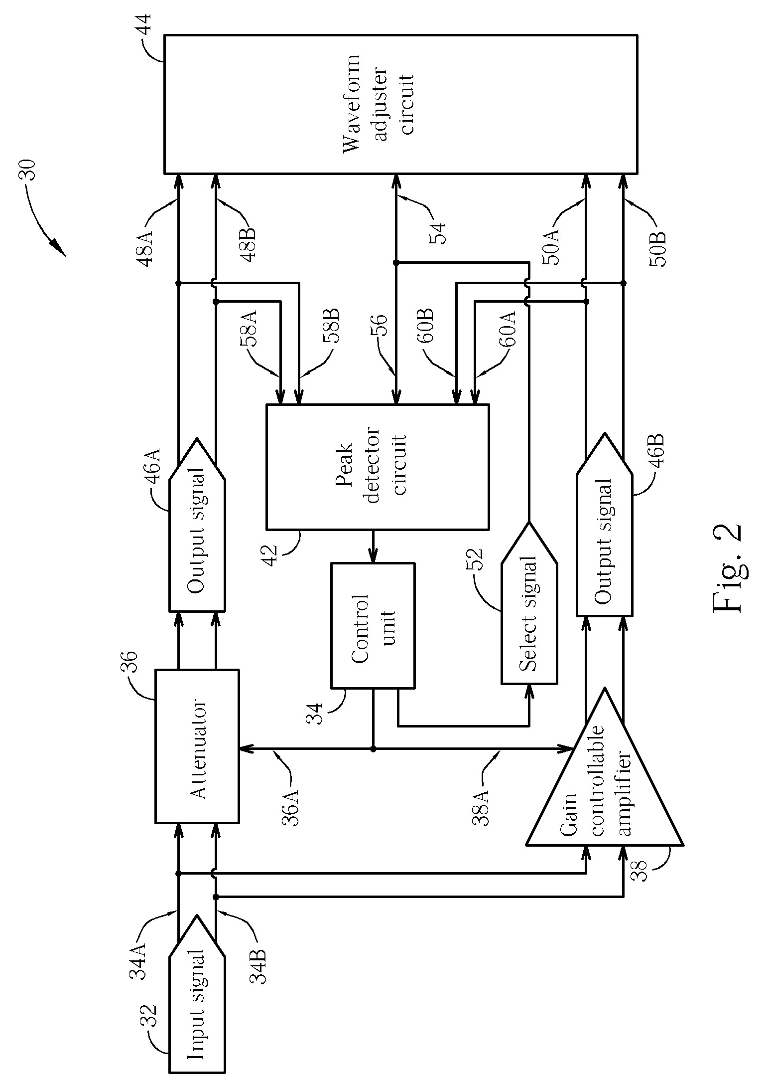
[0019] Please refer to FIG. 2, which is a function block diagram illustrating a signal processing circuit 30 according to the present invention. The signal processing circuit 30 encompasses an attenuator 36, a gain controllable amplifier 38, a control unit 34, a peak detector circuit 42, and a waveform adjuster circuit 44. An input signal 32 fed into the signal processing circuit 30 is in a differential way such that almost all circuit blocks of the signal processing circuit 30 are designed to operate with signals in a differential manner. The gain controllable amplifier 38 and the attenuator 36 are both connected with differential input ends 34A and 34B of the signal processing circuit 30, and both of them couple to the control circuit 34 by means of their control pins 38A and 36A, respectively. The attenuator 36 outputs an output signal 46A to both of the waveform adjuster circuit 44 and the peak detector circuit 42, and the gain controllable amplifier 38 also outputs an output si...


PUM

PropertyMeasurementUnit
bias currentaaaaaaaaaa

Abstract

A signal processing circuit for adjusting an input signal and generating a corresponding digital output signal in an optical disk driver is provided. The signal processing circuit includes an attenuator for receiving and attenuating the input signal and then generating an attenuated output signal; a gain controllable amplifier for receiving and amplifying the input signal and then generating an amplified output signal; a control unit providing a control signal and a select signal, the control signal is directed to the attenuator and the gain controllable amplifier for enabling / disabling the attenuator and the gain controllable amplifier and for controlling their gains such that one of the attenuator and gain controllable amplifier is enabled at a time; and a waveform adjuster circuit for adjusting the amplified / attenuated output signal delivered from the gain controllable amplifier or the attenuator so as to generate the digital signal related to the input signal.

Description

CROSS-REFERENCE TO RELATED DOCUMENTS [0001] The present application is a continuation-in-part of U.S. application Ser. No. 10 / 064,781, entitled Signal Processing Circuit for Optical Disc Drivers and the Related Method, filed Aug. 16, 2002.BACKGROUND OF THE INVENTION [0002] 1. Field of the Invention [0003] The present invention relates to a signal processing circuit for adjusting signal amplitude, and more particularly, to a signal processing circuit that selectively enables an attenuator or a gain controllable amplifier coupled in parallel so as to reduce power consumption when converting signal formats of related input signals. [0004] 2. Description of the Related Art [0005] The most important characteristics of the modern information society is that every kind of information and knowledge is transmitted, stored, or manipulated in the form of electrical signals. Information in an electrical signal form can be accumulated and be exchanged rapidly, and technology keeps progressing ba...

Claims


Application Information

Patent Timeline
Patent Type & Authority Applications(United States)
IPC IPC(8): G11B3/00G11B5/09G11B20/10
CPCG11B20/10009G11B20/10314G11B20/10046G11B20/10027
Inventor LIN, JYH-FONGHSIEH, YI-BINCHIEN, CHIH-CHANG
Owner VIA TECH INC
Why Eureka
Try Eureka