
Pulse signal generator

A pulse signal and generator technology, which is applied in the field of interference signal generation devices, can solve problems such as short action time, pulse signal generators cannot output rise time, and cannot be used to evaluate the ability of electronic equipment to resist electromagnetic pulse interference. Short, flexible, and steep-edged effects

Active Publication Date: 2014-04-23
陕西海泰电子有限责任公司
View PDF5 Cites 8 Cited by
  • Summary
  • Abstract
  • Description
  • Claims
  • Application Information

AI Technical Summary

Problems solved by technology

[0004] In order to solve the technical problem that the existing pulse signal generator cannot output pulse signals with fast rise time, short action time and large amplitude dynamic range, and cannot be used to evaluate the anti-electromagnetic pulse interference ability of electronic equipment, the present invention provides a pulse signal generator It can generate a pulse signal generating device with fast rise time, short action time and large amplitude dynamic range to meet the needs of anti-jamming performance evaluation of electronic equipment

Method used


Image

  • Pulse signal generator
  • Pulse signal generator
  • Pulse signal generator

Examples


Embodiment Construction

[0047] The specific embodiments of the present invention will be described in detail below in conjunction with the accompanying drawings, but the embodiments of the present invention are not limited thereto.

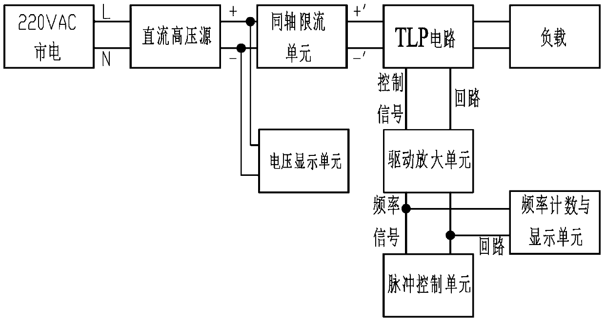
[0048] The pulse signal generator is realized by transmission line. like figure 1 As shown, the pulse signal generator is composed of a DC high voltage source, a voltage display unit, a coaxial current limiting unit, a TLP circuit (TLP, transmission-line pulse), a pulse control unit, a drive amplifier unit, a frequency counting and display unit. in:

[0049] The DC high voltage source converts AC mains power into DC power, and the output DC voltage is continuously adjustable, and the DC high voltage source provides working voltage for the TLP circuit. The voltage display unit is used to display the output DC voltage of the DC high voltage source, and the coaxial current limiting unit is used to control the charging current of the TLP circuit.

[0050] The TLP circuit ...


PUM


Abstract

The invention relates to a pulse signal generator comprising a DC high voltage source, a voltage display unit, a coaxial current-limiting unit, a TLP circuit, a pulse control unit, a drive amplification unit and a frequency counting and display unit. The DC high voltage source is used for converting alternating current commercial power into continuously adjustable direct current. The coaxial current-limiting unit is used for controlling size of charging current of the TLP circuit which is used for generating a nanosecond-level high current pulse signal. A frequency signal outputted by the pulse control unit is amplified by the drive amplification unit and then controls a working mode of the TLP circuit. The frequency counting and display unit counts and displays the frequency signal generated by the pulse control unit. A situation that existing pulse signal generators cannot output pulse signals which are rapid in rising period of time and short in action time is solved by the pulse signal generator. The pulse signal generator is the device capable of generating the pulse signal which is rapid in rising period of time, short in action time and wide in amplitude dynamic range so that a requirement of anti-interference performance assessment of an electronic device can be met.

Description

technical field [0001] The invention relates to an interference signal generation device, in particular to a pulse signal device capable of generating a pulse signal with fast rising time and falling time, short action time and large amplitude dynamic range. Background technique [0002] With the development of electronic technology, all kinds of equipment are generally electrified. The anti-interference performance of electronic equipment has attracted more and more attention. Of course, the anti-interference performance of the designed and manufactured electronic equipment can be determined by testing it in various on-site noise environments. However, since the disturbances generated in the field are mostly accidental and random, the test takes a long time and is likely not to be repeated. Once it occurs, it is often too late to use various means to find out which part of the circuit has malfunctioned. Therefore, there is a need for an interference source device, which ...

Claims


Application Information

Patent Timeline
IPC IPC(8): H03K3/02
Inventor 郭恩全王浩苗胜张海东
Owner 陕西海泰电子有限责任公司
Learn More