Interphone

A walkie-talkie and ontology technology, which is applied in two-party line system stations, electrical components, transmission systems, etc., can solve the problems of no display screen, inconsistent radio frequency, and the inability to communicate with walkie-talkies, etc., and achieve the effect of reducing production costs

Inactive Publication Date: 2016-11-09
南安市吉野电子科技有限公司
3 Cites 3 Cited by

AI-Extracted Technical Summary

Problems solved by technology

The above general limitations have also brought a lot of trouble to the promotion and use of walkie-talkies and daily maintenance.
The reason for the above-mentioned problems is mainly that the RF frequencies between the walkie-talkies with general limitations are inconsistent, and the sub-audio frequency is inconsistent.
[0003] I...

Method used

Further, the present invention sets high-frequency frequency divider 3, carries out frequency division by high-frequency frequency divider 3, and then conver...

Abstract

The invention discloses an interphone. The interphone comprises an interphone body. The interphone body is equipped with a shell, and an MCU controller, a baseband processor, an MIC microphone and a loudspeaker which are integrally mounted in the shell. The interphone body also comprises a memory, and an LCD screen for displaying radio frequency information and mute audio information. Bidirectional connection is carried out between the memory and the MCU controller. The LCD screen is connected with the output end of the MCU controller. Compared with a traditional technology, the interphone has the advantages that the interphone is equipped with the LCD screen for directly displaying the radio frequency information and the mute audio information from the interphone. Conditions are provided for normal communication among different interphones. The other interphones can carry out corresponding settings through the radio frequency information and mute audio information, and carry out conversations with the interphone.

Application Domain

TransmissionStations for two-party-line systems

Technology Topic

Radio frequencyLoudspeaker +6

Image

  • Interphone

Examples

  • Experimental program(1)

Example Embodiment

[0017] In order to further explain the technical solution of the present invention, the present invention will be described in detail below through specific embodiments.
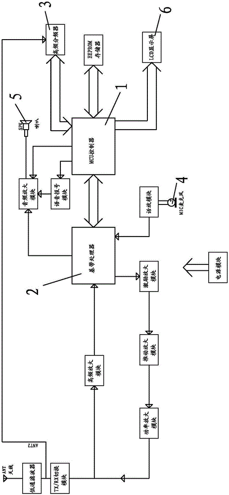
[0018] Such as figure 1 As shown, the present invention provides a walkie-talkie, including a walkie-talkie body, the walkie-talkie body has a housing, and an MCU controller 1, a baseband processor 2, a high-frequency divider 3, a MIC microphone 4, and a speaker integrated in the housing. Speaker 5. The walkie-talkie body receives and sends signals through the antenna. MCU controller 1 is bidirectionally connected with baseband processor 2 and high frequency divider 3, and the antenna is connected to the input end of the baseband processor through a low-pass filter, TX/RX switching module and high frequency amplifier module in turn, and the antenna It is also connected to the input end of the high frequency divider through a low pass filter. The output terminal of the MCU controller 1 is directly connected to the speaker speaker 5 through the audio amplifier module, or the output terminal of the MCU controller 1 is connected to the speaker speaker 5 through the voice reporting module and the audio amplifier module in turn. The output end of the baseband processor 2 is also connected to the speaker speaker 5 through the audio amplifier module. The MIC microphone 4 is connected to the input terminal of the baseband processor 2 through a speech amplifier module. The output end of the baseband processor 2 is connected to the antenna through the excitation amplifier module, the push amplifier module, the power amplifier module, the TX/RX switching module and the low pass filter in sequence.
[0019] The high frequency divider 3 has three selectable frequency division ratios, which are divided by 64, divided by 128 and divided by 256. The frequency division ratio selection and frequency division execution of the high frequency divider 3 are driven and controlled by the MCU controller 1. The MCU controller 1 has a memory, which can be used for data storage. The memory is bidirectionally connected with the MCU controller 1. The output terminal of the MCU controller 1 is connected with an LCD display screen 6 which is arranged on the shell of the walkie-talkie body. The invention is also connected with a power module, and the power module provides working power for the normal operation of the whole walkie-talkie. And there is a power on-off switch on the output circuit of the power module to realize the opening and closing of the walkie-talkie. Three frequency bands corresponding to the three selectable frequency division ratios of the high frequency divider 3 are preset in the MCU controller 1. The baseband processor 2 can measure the mute tone frequency based on the radio frequency signal. The shell of the walkie-talkie body is also equipped with conventional function keys in the industry to adjust the volume.
[0020] When receiving the signal, the antenna receives the radio frequency signal from the other party's walkie-talkie. The radio frequency signal passes through the low-pass filter and enters the high frequency divider 3. It is rectified by the high frequency divider 3 to transform the sine wave into a square wave signal. The square wave signal is sent to the MCU controller 1, and the MCU controller 1 quickly detects the radio frequency signal, and initially determines which of the above three frequency bands its radio frequency falls, so as to select the corresponding frequency division ratio, and select this The information is sent to the high-frequency divider 3. The high-frequency divider 3 executes the frequency division signal of the MCU controller 1, and divides the radio frequency signal. After the frequency division is over, the high frequency divider 3 divides the frequency The information is sent to the MCU controller 1, and the MCU controller 1 finally measures the divided radio frequency more accurately. The data is stored in the memory and displayed on the LCD display 6.
[0021] At the same time, the RF signal received by the antenna passes through a low-pass filter, and then undergoes TX/RX switching and high-frequency amplification before entering the baseband processor 2. The MCU controller 1 sends the frequency-divided RF information to the baseband processor 2, and baseband processing The device 2 measures the mute frequency of the received radio frequency signal based on this radio frequency information, and the baseband processor 2 sends the mute frequency of the radio frequency signal to the MCU controller 1, and the data is stored in the memory and displayed on the LCD display 6. Show in.
[0022] The radio frequency signal is converted into an audio signal by the MCU controller 1, and the audio signal is sequentially processed by the voice reporting module and audio amplified before being transmitted to the horn speaker 5 to realize voice reporting.
[0023] When a signal is sent, the sound comes in from the MIC microphone 4, and the MIC microphone 4 converts the audio signal into an electrical signal, which is processed by the speech amplifier module and sent to the baseband processor 2. It is further output from the output terminal of the baseband processor 2, and is transmitted to the antenna after excitation amplification, push amplification, power amplification, TX/RX switching and low-pass filter processing, and then transmitted through the antenna.
[0024] Compared with the traditional technology, the present invention is equipped with an LCD display screen 6, which can directly display the radio frequency and mute frequency from the other party's walkie-talkie. To create conditions for the normal communication between different walkie-talkies, other walkie-talkies can be set accordingly through this radio frequency and mute tone frequency, and talk to this walkie-talkie.
[0025] Further, the present invention is provided with a high-frequency divider 3, which is divided by the high-frequency divider 3, and then converted into a low radio frequency, so as to reduce the performance requirements of related electronic devices, such as the MCU controller 1, and reduce production costs.
[0026] The above-mentioned embodiments and drawings do not limit the product form and style of the present invention, and any appropriate changes or modifications made by those of ordinary skill in the art should be regarded as not departing from the patent scope of the present invention.

PUM

no PUM

Description & Claims & Application Information

We can also present the details of the Description, Claims and Application information to help users get a comprehensive understanding of the technical details of the patent, such as background art, summary of invention, brief description of drawings, description of embodiments, and other original content. On the other hand, users can also determine the specific scope of protection of the technology through the list of claims; as well as understand the changes in the life cycle of the technology with the presentation of the patent timeline. Login to view more.

Similar technology patents

Classification and recommendation of technical efficacy words

Why Eureka
Try Eureka