Rotational transmission device

A technology of rotation transmission device and relative rotation, applied in the direction of non-mechanical drive clutches, one-way clutches, magnetic drive clutches, etc., can solve problems such as troublesome assembly, instability, difficulty, etc., to prevent magnetic leakage, improve attraction force, overlap The effect of volume increase

Active Publication Date: 2016-11-09
NTN CORP
View PDF1 Cites 1 Cited by
  • Summary
  • Abstract
  • Description
  • Claims
  • Application Information

AI Technical Summary

Problems solved by technology

[0009] However, in the conventional rotation transmission device described in the above-mentioned Patent Document 1, since the rotor and the electromagnet are separately attached to the input shaft, assembly is troublesome, and there is still room for improvement.
[0010] In addition, since the axial positioning parts of the rotor and the electromagnet are provided at intervals in the axial direction, the axial overlap amount between the outer cylinder part of the rotor and the iron core of the electromagnet incorporated inside will be reduced. Since it is not constant due to tolerances and mounting errors, it is difficult to manage the overlapping amount, and it is impossible to stabilize the attractive force borne by the armature.
Therefore, there is still room for improvement in realizing the ease of management of the amount of overlap

Method used


Image

  • Rotational transmission device
  • Rotational transmission device
  • Rotational transmission device

Examples


Embodiment Construction

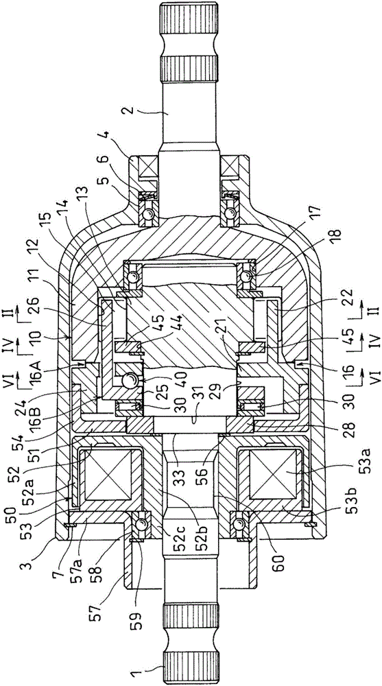
[0033] Embodiments of the present invention will be described below based on the drawings. figure 1 An embodiment of the rotation transmission device according to the present invention is shown. As shown in the figure, the rotation transmission device includes an input shaft 1, an output shaft 2 arranged coaxially with the input shaft 1, a housing 3 covering the shaft ends of the two shafts, which is inserted into the housing 3 and carried out. A two-way clutch 10 that transmits or blocks rotation from the input shaft 1 to the output shaft 2 , and an electromagnetic clutch 50 that controls engagement and release of the two-way clutch 10 .

[0034] The housing 3 is formed in a cylindrical shape, and a small-diameter bearing tube 4 is provided at one end thereof, and the output shaft 2 is rotatably supported by a bearing 5 incorporated in the bearing tube 4 . In addition, an elastic member 6 made of a disc spring is installed in the bearing cylinder 4, and the elastic member 6 ...


PUM


Abstract

An electromagnetic clutch (50) comprises an armature (51), a rotor (52) having an outer cylindrical portion (52a) and an inner cylindrical portion (52b), and an electromagnet (53), a bearing support cylinder (57) being provided on the outer end surface of a core (53b) that supports an electromagnetic coil (53a) of the electromagnet (53), a bearing (58) being incorporated into the inside of the bearing support cylinder (57) and being positioned and retained in the axis direction thereof. A small diameter cylindrical portion (52c) provided on an end of the inner cylindrical portion (52b) of the rotor (52) is press-fitted into the bearing (58) such that the rotor (52) and the electromagnet (53) form one unit, thereby improving ease of assembly of the electromagnetic clutch (50) and improving ease of management of the amount of overlap between the outer cylindrical portion (52a) of the rotor (52) and the core (53b) of the electromagnet (53).

Description

technical field [0001] The present invention relates to a rotation transmission device for switching between transmission and disconnection of rotation between an input shaft and an output shaft. Background technique [0002] As a rotation transmission device that transmits and blocks rotation from an input shaft to an output shaft, a rotation transmission device that has a two-way clutch and controls engagement and release of the two-way clutch by an electromagnetic clutch is known. [0003] In the rotation transmission device described in the following patent document 1, the control cage and the rotation cage are incorporated into the outer ring and the part of the outer ring so that the column parts provided on each cage are alternately arranged in the circumferential direction. Between the inner inner rings, a pair of opposing rollers are inserted into the pockets formed between the adjacent column parts, and the pair of rollers are fixed by the elastic member inserted b...

Claims


Application Information

Patent Timeline
Patent Type & Authority Applications(China)
IPC IPC(8): F16D27/10F16D41/08
CPCF16D27/06F16D41/067F16D2023/123F16D41/088F16D41/086
Inventor 北山直嗣石川慎太朗佐藤光司斋藤隆英
Owner NTN CORP
Why Eureka
Try Eureka