
Transformer device and measurement system formed therewith

A transducer and equipment technology, applied in the direction of specific gravity measurement, measurement capacity, measurement device, etc., can solve problems such as measurement error

Active Publication Date: 2016-11-09
ENDRESS HAUSER FLOWTEC AG
View PDF16 Cites 10 Cited by
  • Summary
  • Abstract
  • Description
  • Claims
  • Application Information

AI Technical Summary

Problems solved by technology

Furthermore, the inventors have also detected that the aforementioned thermal coupling can sometimes reach a point where it is no longer practically possible with regard to the degree of high precision of measurement expected for measuring systems of the type in question, especially for electro-vibratory measuring systems. Ignore, respectively, on the contrary, in particular also the time constant target temperature sometimes deviates from the actual (correspondingly true) target temperature by more than 0.5, for example in the manner in which the measured value for the target temperature is determined by the corresponding measuring system in different cases In the case of K, the corresponding neglect of the influence of such a temperature difference on the respectively recorded temperature of the measuring location (and accordingly the temperature measurement signal representing this temperature difference) can lead to very significant measurement errors

Method used


Image

  • Transformer device and measurement system formed therewith
  • Transformer device and measurement system formed therewith
  • Transformer device and measurement system formed therewith

Examples


Embodiment Construction

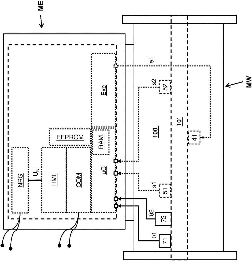
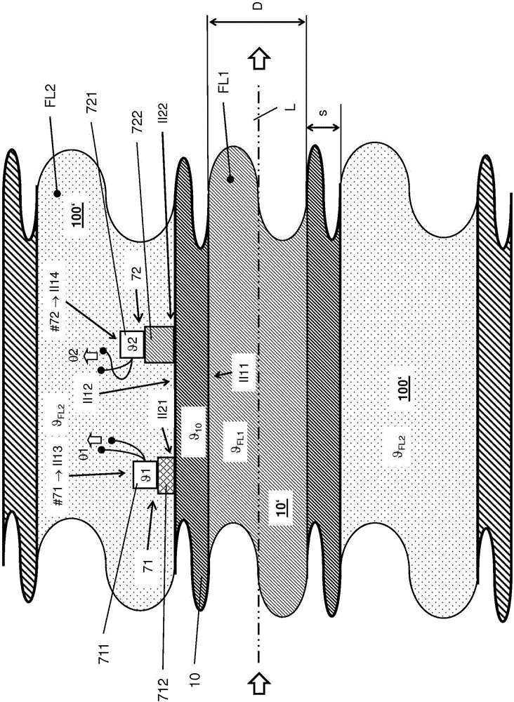
[0054] figure 1 Schematic illustration for measuring fluid temperature with a measurement A measurement system of at least one measured variable x (which may be a time variable in a given case) of a flow fluid FL1 (measurement fluid) such as a gas, liquid or flowable diffuser. The measuring system is used to cyclically determine the measured value X that instantaneously represents the measured variable x . The measured variable x can be, for example, density or viscosity and is thus a measured variable that has a certain correlation with the corresponding measured fluid temperature and / or is converted into the corresponding measured value x x In the case of transducer devices, temperature-dependent measurement errors are caused. However, the measured variable can also be, for example, a temperature of interest (hereinafter also referred to as target temperature) at a device reference point (poi) predetermined for the measurement system and located within the transducer dev...


PUM

PropertyMeasurementUnit
specific heat capacityaaaaaaaaaa
heat capacityaaaaaaaaaa
thicknessaaaaaaaaaa

Abstract

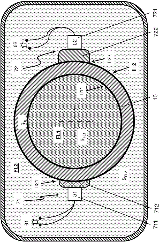
The invention relates to a transformer device comprising a transformer housing (100), a pipe (10), a temperature sensor (71), and a temperature sensor (72). The pipe is arranged within a cavity of the transformer housing such that, between an inner surface (100+) of a wall of the transformer housing facing the cavity and a shell surface (10#) of a wall of the pipe facing the cavity, an intermediate chamber (100') is formed. Furthermore, the pipe is designed to conduct a fluid (FL1) in the lumen thereof such that an inner surface (10+) of the wall of the pipe facing said lumen contacts the fluid conducted in the lumen. Each of the temperature sensors (71; 72) is formed by a temperature sensor (711; 721) arranged within the intermediate chamber (100') and by a coupling element (712; 722) coupling the temperature sensor (711; 721) to the wall of the pipe in a thermally conductive manner and is additionally designed to detect a measurement point temperature ([theta]1; [theta]2), namely a temperature at a first or second temperature measurement point formed by the temperature sensor (711; 721) and to transform said temperature into a corresponding temperature measurement signal ([theta]1; [theta]2), namely an electrical measurement signal representing the measurement point temperature ([theta]1; [theta]2).

Description

technical field [0001] The invention relates to a transducer device suitable for measuring the target temperature of the transducer device, as well as the time-variable target temperature, in particular the temperature of a fluid guided in the lumen of a tube, and / or such a device in contact with the fluid The temperature of the wall of the tube. Furthermore, the invention also relates to a measuring system formed by means of such a transducer arrangement. Background technique [0002] A transducer of the type in question comprises: a transducer housing having a cavity enclosed by a wall (usually metal) and a tube having an inner cavity surrounded by a wall (usually metal) and the following Arranged in the cavity of the transducer housing in the above manner: between the inner surface of the wall of the transducer housing facing the cavity and the outer surface of the wall of the tube (ie, the outer surface of the wall of the tube facing the cavity) There is an intermediat...

Claims


Application Information

Patent Timeline
Patent Type & Authority Applications(China)
IPC IPC(8): G01F1/84G01N9/00
CPCG01F1/849G01N11/16G01F15/02G01F15/14G01N2009/006G01N2011/0013G01F1/8413G01F1/8409G01N9/002
Inventor 阿尔弗雷德·里德朱浩恩尼奥·比托格哈德·埃克特约瑟夫·胡本施泰纳迈克尔·维斯曼林遥婴
Owner ENDRESS HAUSER FLOWTEC AG
Learn More