Pressure Sensor Chip
A pressure sensor and sensor technology, applied in the direction of measuring fluid pressure, instruments, and pressure difference measurement between multiple valves, to achieve the effects of ensuring pressure resistance, reducing stress generation, and preventing diaphragm edge concentration
- Summary
- Abstract
- Description
- Claims
- Application Information
AI Technical Summary
Problems solved by technology
Method used
Image

Examples
Embodiment approach 1
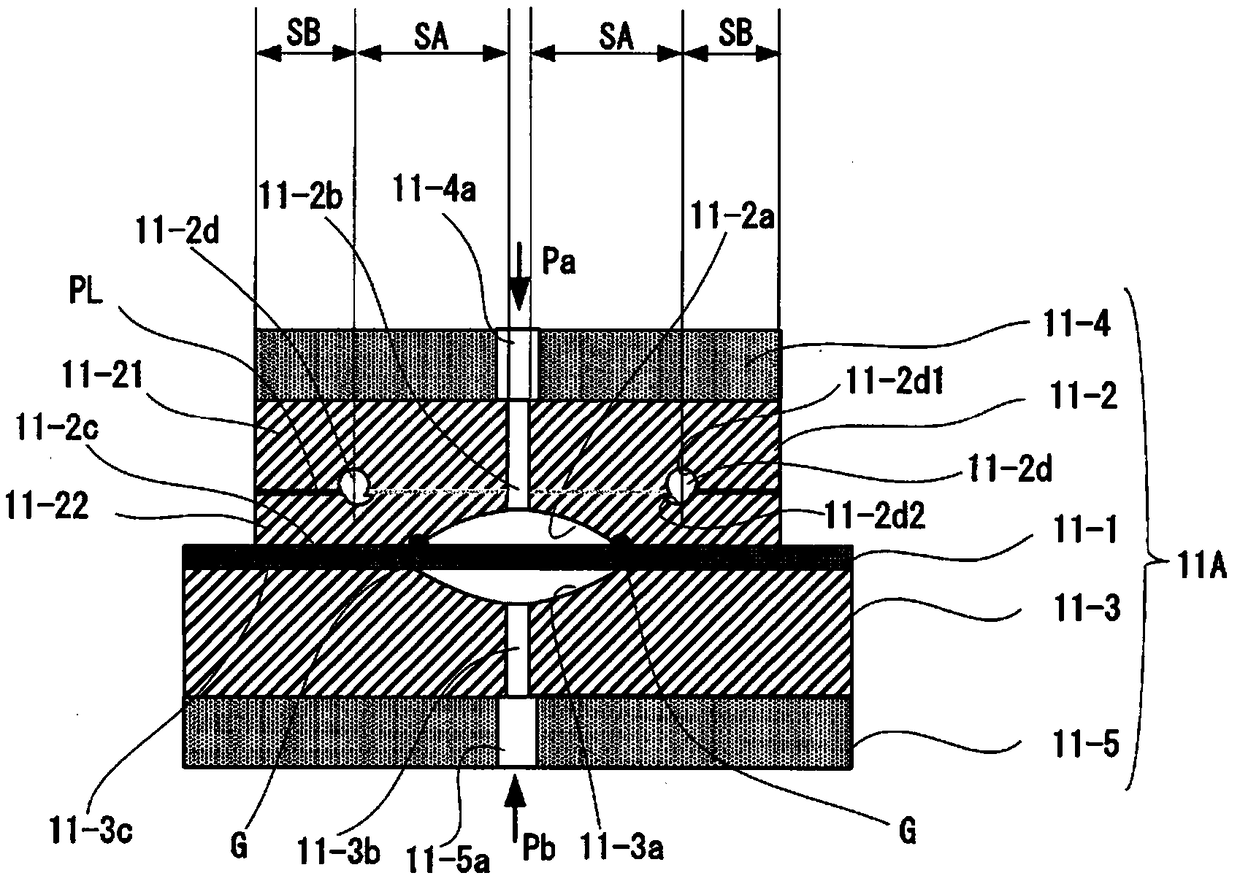
[0053] figure 1 It is a diagram showing the outline of the first embodiment (Embodiment 1) of the pressure sensor chip of the present invention.
[0054] exist figure 1 In the pressure sensor chip 11A shown, 11-1 is a sensor diaphragm, 11-2 and 11-3 are first and second stopper members as holding members bonded across the sensor diaphragm 11-1, and 11-4 and 11-5 are the 1st and 2nd bases joined to the stopper members 11-2 and 11-3. The blocking members 11-2, 11-3 and the bases 11-4, 11-5 are made of silicon, glass, or the like.
[0055] In this pressure sensor chip 11A, recessed portions 11-2a, 11-3a are respectively formed on the surfaces of the barrier members 11-2, 11-3 bonded to one surface and the other surface of the sensor diaphragm 11-1. The recessed portion 11-2a of the blocking member 11-2 is made to face one side of the sensor diaphragm 11-1, and the recessed portion 11-3a of the blocking member 11-3 is made to face the other face of the sensor diaphragm 11-1. ...
Embodiment approach 2
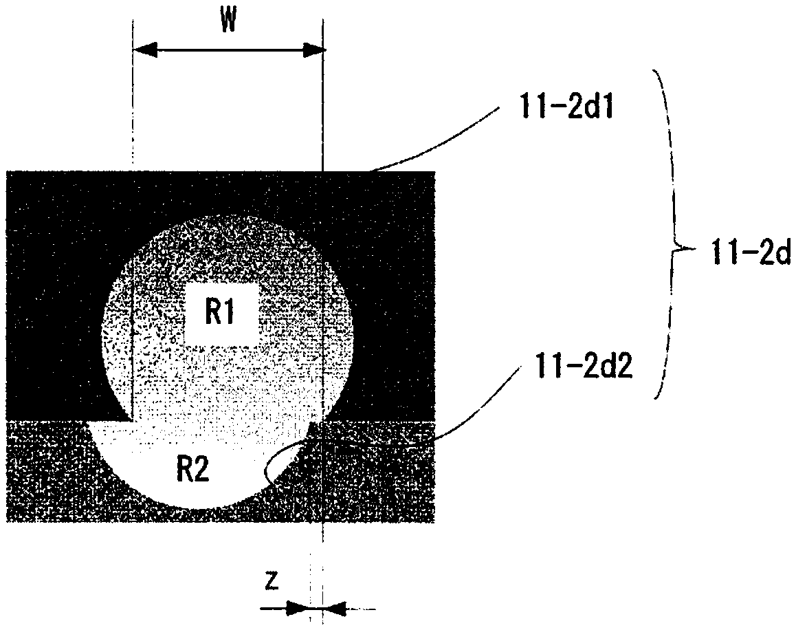
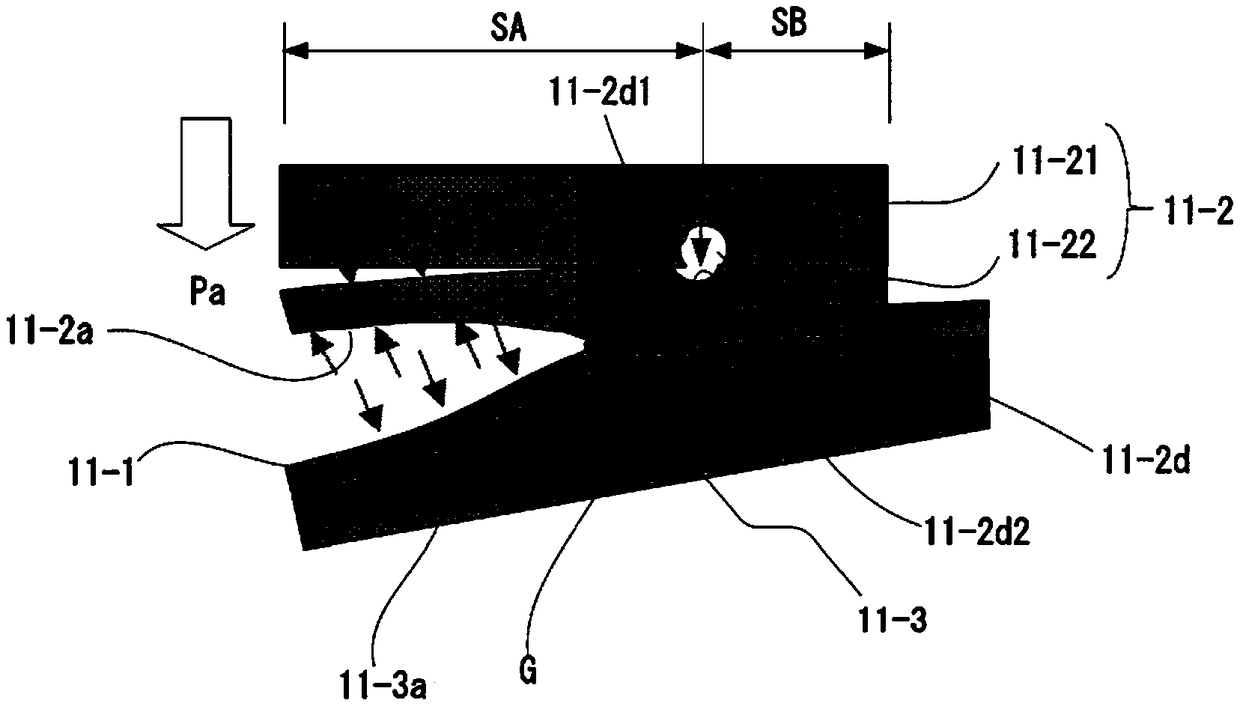
[0075] exist Figure 8 The outline of the second embodiment (Embodiment 2) of the pressure sensor chip of the present invention is shown in . Like the pressure sensor chip 11A of the first embodiment, the pressure sensor chip 11B of the second embodiment includes a non-joining area SA and an annular groove 11-2d continuous with the non-joining area SA inside the barrier member 11-2. , but differs from the pressure sensor chip 11A of Embodiment 1 in the following points.
[0076] In this pressure sensor chip 11B, the region S1 of the peripheral edge portion 11-2c of the barrier member 11-2 facing the sensor diaphragm 11-1 includes an outer peripheral region S1a and an inner peripheral region S1b. The region S1a on the outer peripheral side is a bonding region bonded to one surface of the sensor diaphragm 11-1, and the region S1b on the inner peripheral side is a non-bonding region not bonded to one surface of the sensor diaphragm 11-1.
[0077] In addition, a region S2 facing...
Embodiment approach 3
[0084] Figure 9 It is a diagram showing the outline of a third embodiment (Embodiment 3) of the pressure sensor chip of the present invention.
[0085] exist figure 1 , Figure 7 , Figure 8 In the example shown, the non-joint area SA is provided only inside the blocking member 11-2, but it may also be, for example, Figure 9 As shown as the pressure sensor chip 11C of the third embodiment, the non-joining area SA is also provided inside the stopper member 11-3, and the annular groove 11-3d is provided continuously to the non-joining area SA.
[0086] In the pressure sensor chip 11C according to Embodiment 3, the annular groove 11-2d provided inside the blocking member 11-2 and the annular groove 11-3d provided inside the blocking member 11-3 are set as The same cross-sectional shape is provided opposite to the same position, but the cross-sectional shape of the annular grooves 11-2d and 11-3d can be changed, and the lateral position of the annular grooves 11-2d and 11-3...
PUM
 Abstract
Description
Claims
Application Information
 - R&D
- Intellectual Property
- Life Sciences
- Materials
- Tech Scout
- Unparalleled Data Quality
- Higher Quality Content
- 60% Fewer Hallucinations
Browse by: Latest US Patents, China's latest patents, Technical Efficacy Thesaurus, Application Domain, Technology Topic, Popular Technical Reports.
© 2025 PatSnap. All rights reserved.Legal|Privacy policy|Modern Slavery Act Transparency Statement|Sitemap|About US| Contact US: help@patsnap.com