Massage device for hip massage robot based on redundant drive double parallel mechanisms
A dual-parallel, robot technology, applied in massage auxiliary products, roller massage, physical therapy and other directions, can solve the problems of large exercise space for massage execution, incomplete massage contact, and insignificant massage effect, and achieves small exercise space, Good massage effect and the effect of improving force operation performance
- Summary
- Abstract
- Description
- Claims
- Application Information
AI Technical Summary
Problems solved by technology
Method used
Image

Examples
Embodiment Construction
[0021] In order to make the technical means, creative features, goals and effects achieved by the present invention easy to understand, the present invention will be further described below in conjunction with specific illustrations.
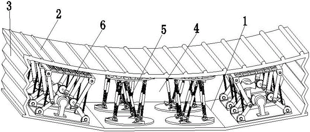
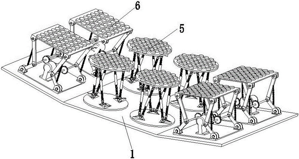
[0022] Such as figure 1 and figure 2As shown, a massage device for a hip massage robot based on a redundant drive double parallel mechanism, including a lower support plate 1, an upper support plate 2, a left and right side plate 3, a front and rear side plate 4, a six-degree-of-freedom massage actuator 5 and a three-freedom degree of massage actuator 6, the number of left and right side plates 3 and front and rear side plates 4 is two, and the number of six degrees of freedom massage actuator 5 and three degrees of freedom massage actuator 6 is four; the lower support plate 1 is composed of Four rectangular plates are spliced into an arc-shaped structure, and the four rectangular plates are connected by hinges. The lower support plate 1 can...
PUM
 Abstract
Description
Claims
Application Information
PatSnap Eureka turns technology decisions into work you can execute. Powered by our Innovation Knowledge Graph, it runs expert workflows across engineering, life sciences, materials and intellectual property. Get your review-ready output in minutes.


