Flat-plate suspending bag centrifugal machine

A centrifuge and plate technology, which is applied to centrifuges, centrifuges with rotating drums, etc., can solve the problem of high manufacturing cost and achieve the effects of low manufacturing cost and simple structure.

Inactive Publication Date: 2016-11-16
张家港市永达机械制造有限公司
View PDF6 Cites 4 Cited by
  • Summary
  • Abstract
  • Description
  • Claims
  • Application Information

AI Technical Summary

Problems solved by technology

[0002] The upper port of the drum of the flat hanging bag centrifuge currently on the market is equipped with a hanging plate part with a filter bag installed, and the hanging plate part is detachably installed on the upper end of the drum through a connecting piece. When the centrifuge is working, the hanging plate parts and the drum rotate together. When the flat-panel hanging bag centrifuge stops working, it is necessary to remove the connecting parts, and then use the special lifting device used with the hanging plate parts to lift the hanging plate parts from the flat plate. The drum of the hanging bag centrifuge is lifted from the drum. The flat hanging bag centrifuge with this structure needs to process the hanging plate parts and special lifting device, so the manufacturing cost is high.

Method used


Image

  • Flat-plate suspending bag centrifugal machine
  • Flat-plate suspending bag centrifugal machine

Examples


Embodiment Construction

[0014] Specific embodiments of the present invention will be described in detail below in conjunction with the accompanying drawings.

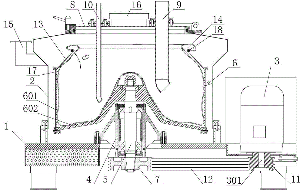
[0015] Such as figure 1 The flat hanging bag centrifuge shown comprises a horizontal flat base 1, a casing 2 arranged on the flat bottom 1, and a driving device 3 arranged on one side of the casing 2, and the casing 2 is provided with There is a shaft seat 4 connected to the flat base 1, and a rotating shaft 5 is arranged vertically inside the shaft seat 4. The upper end of the rotating shaft 5 protrudes outside the shaft seat 4 and is sleeved with a rotating drum 6. The lower end of the rotating shaft 5 passes through the flat plate downwards. Outside the machine base 1, a driven pulley 7 is sleeved. The top of the casing 2 is open, and a top cover 8 is arranged at the opening. The top cover 8 is provided with a feed pipe 9 inserted into the drum 6 from the outside and The flushing pipe 10, the output shaft 301 of the driving device 3 passes...


PUM


Abstract

The invention discloses a flat-plate suspending bag centrifugal machine. The centrifugal machine comprises a flat-plate machine base, a shell and a driving device, wherein a shaft seat is arranged in the machine shell, a rotating shaft is arranged in the shaft seat, the upper end of the rotating shaft is sleeved with a rotating drum, the lower end of the rotating shaft is sleeved with a driven belt wheel, an opening is formed in the top of the shell, a top cover is arranged on the opening of the shell, the top cover is provided with a feeding pipe and a flushing pipe, the output shaft of the driving device vertically and downwards penetrates out of the flat-plate machine base and is sleeved with a driving belt wheel, the driving belt wheel and the driven belt wheel transmit power through a belt, the rotating drum comprises a cylinder body and a bottom plate, the rotating shaft is connected to the center of the bottom plate, the upper end of the cylinder is connected with a conical cylindrical liquid blocking plate, the diameter of the upper end of the liquid blocking plate is smaller than that of the lower end, a fixing ring used for fixing a suspending bag is arranged on the outer side wall of the liquid blocking plate, the opening portion of the suspending bag can be turned outwards to the lower portion of the fixing ring and then is fixed through a rope. According to the invention, a suspending plate part for fixing the suspending bag and a special hoisting device do not need to be processed, so that the structure is simple, and the manufacturing cost is low.

Description

technical field [0001] The invention relates to a centrifugal device, in particular to a flat-plate hanging bag centrifuge. Background technique [0002] The upper port of the drum of the flat hanging bag centrifuge currently on the market is equipped with a hanging plate part with a filter bag installed, and the hanging plate part is detachably installed on the upper end of the drum through a connecting piece. When the centrifuge is working, the hanging plate parts and the drum rotate together. When the flat-panel hanging bag centrifuge stops working, it is necessary to remove the connecting parts, and then use the special lifting device used with the hanging plate parts to lift the hanging plate parts from the flat plate. The drum of the hanging bag centrifuge is lifted from the drum. The flat hanging bag centrifuge with this structure needs to process the hanging plate parts and special lifting device, so the manufacturing cost is high. Contents of the invention [000...

Claims


Application Information

Patent Timeline
IPC IPC(8): B04B7/00B04B1/00
CPCB04B7/00B04B1/00
Inventor 马爱忠王莉刘浩
Owner 张家港市永达机械制造有限公司
Why Eureka
Try Eureka