Rapid-replacement high-precision gang cutter and machining method thereof

A technology that combines milling cutters and processing methods, applied in milling cutters, metal processing equipment, manufacturing tools, etc., can solve the problems of unreasonable utilization of tool resources, inadequate coordination of tool heads and tool holders, and reduced processing efficiency of workpieces. The effect of reducing re-calibration steps, improving tool carrying capacity, and improving tool change efficiency

Inactive Publication Date: 2016-11-16
锑玛(苏州)精密工具股份有限公司
View PDF8 Cites 11 Cited by
  • Summary
  • Abstract
  • Description
  • Claims
  • Application Information

AI Technical Summary

Problems solved by technology

[0002] Existing knives include two parts: the cutter head and the handle. The cutter head and the handle are generally formed by welding or integrally formed. No matter which form, the cutter needs to be replaced after the cutter head is worn out, while the handle is intact. In order to ensure the normal operation of the processed workpiece, the tool needs to be replaced frequently, which leads to the unreasonable use of tool resources and increases the processing cost
[0003] With the continuous increase of people's requirements for the low cost of tool processing, the cutter head and the handle ha

Method used


Image

  • Rapid-replacement high-precision gang cutter and machining method thereof
  • Rapid-replacement high-precision gang cutter and machining method thereof
  • Rapid-replacement high-precision gang cutter and machining method thereof

Examples


Embodiment

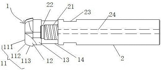
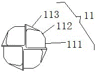
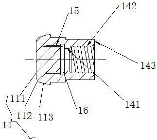
[0033] Such as Figure 1-5 A quick-change high-precision combined milling cutter and its processing method are shown, including a cutter head 1 and a handle 2, characterized in that: the cutter head 1 is a cutting edge 11 from the end to the tail, and the chip removal groove 12. The space-avoiding part 13, the high-speed steel substrate 14, the number of the cutting edges 111 is 4 and they are symmetrically arranged at the end of the cutter head 1. The chip removal groove 12 is located between the two cutting edges 11. The cutting The edge 11 includes a cutting edge I111, a cutting edge II112, and a cutting edge III113. The cutting edge II112 is arranged between the cutting edge I111 and the cutting edge III113. and the high-speed steel substrate 14 are fixed by high-temperature welding. The high-speed steel substrate 14 is provided with an axial positioning hole 141, a threaded hole 142 and a radial positioning surface 143. The axial positioning hole 141 is arranged at the fr...


PUM

PropertyMeasurementUnit
Widthaaaaaaaaaa

Abstract

The invention provides a rapid-replacement high-precision gang cutter and a machining method thereof. The rapid-replacement high-precision gang cutter comprises a cutter head and a cutter handle. The cutter head is provided with four cutting edges, chip grooves, an avoiding part and a high-speed steel base body from the end to the tail in sequence. The four cutting edges are symmetrically arranged at the end of the cutter head in pairs. The chip grooves are located between every two adjacent cutting edges. Each cutting edge comprises a cutting edge body I, a cutting edge body II and a cutting edge body III, and the cutting edge body II is arranged between the cutting edge body I and the cutting edge body III. The avoiding part is arranged behind the cutting edge bodies II. The avoiding part and the high-speed steel base body are fixed through high-temperature welding. The high-speed steel base body is internally provided with an axial positioning hole, a threaded hole and a radial positioning part. The axial positioning hole is formed in the front end of the threaded hole. The front end of the cutter handle is provided with a screw rod matched with the threaded hole. Through the replaceable structural design, materials for machining of the cutter are saved, and the economical performance is high; through the design of the positioning part, the precision of repeated positioning can be improved, and the cutter replacing efficiency can be improved.

Description

technical field [0001] The invention relates to the technical field of cutter processing, in particular to a quick-change high-precision combined milling cutter and a processing method thereof. Background technique [0002] Existing knives include two parts: the cutter head and the handle. The cutter head and the handle are generally formed by welding or integrally formed. No matter which form, the cutter needs to be replaced after the cutter head is worn out, while the handle is intact. In order to ensure the normal operation of the processed workpiece, the tool needs to be replaced frequently, which causes the tool resource to be unreasonably utilized and the processing cost to increase. [0003] With the continuous increase of people's requirements for the low cost of tool processing, the cutter head and the handle have been designed in a split design. When using the tool, the cutter head and the handle are assembled together. , when the cutter head needs to be changed, ...

Claims


Application Information

Patent Timeline
IPC IPC(8): B23C5/22B23C5/28B23P15/34
CPCB23C5/2204B23C5/28B23C2210/203B23P15/34
Inventor 李振丰奚旭东孔小波张明敏
Owner 锑玛(苏州)精密工具股份有限公司
Why Eureka
Try Eureka