Gesture adjusting device

A technology for adjusting devices and attitudes, which is applied in the field of automatic machinery and equipment design, and can solve problems such as cable failure

Inactive Publication Date: 2016-11-16
TSINGHUA UNIV
View PDF6 Cites 17 Cited by
  • Summary
  • Abstract
  • Description
  • Claims
  • Application Information

AI Technical Summary

Problems solved by technology

Although the parallel attitude control mechanism has the characteristics of attitude adjustment function, easy control and high rigidity, it will inevitably cause the rotation of the moving platform around the Z axis during the attitude adjustment process.
This will cause the actuator cables mounted on the moving platform to bear alternating torsional loads for a long time, which will cause the cables to fail

Method used


Image

  • Gesture adjusting device
  • Gesture adjusting device
  • Gesture adjusting device

Examples


Embodiment 1

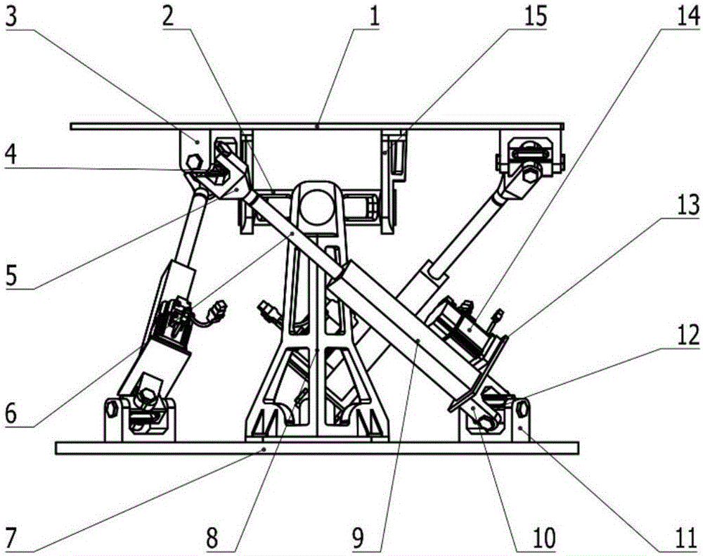
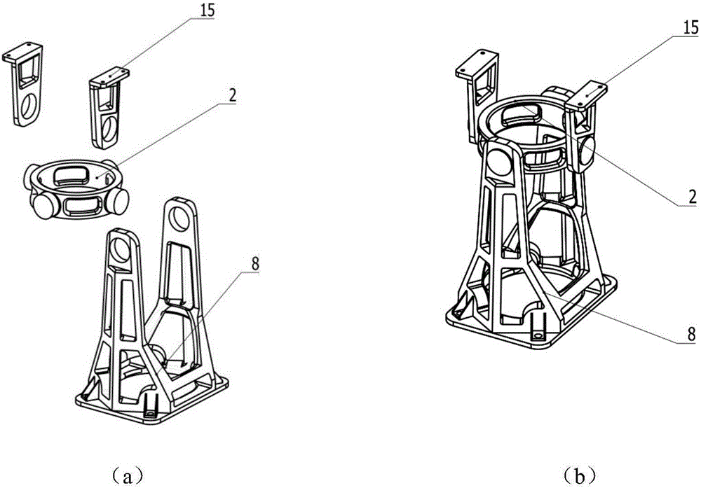
[0024] The structure of a posture adjustment device in this embodiment is as follows: figure 1 As shown, it includes a moving platform 1 installed with an actuator, a fixed platform 7 and the first, second, third, and fourth branch chains, and the four branch chains are respectively connected between the moving platform 1 and the fixed platform 7, and It forms a space closed-loop mechanism with the moving platform 1 and the fixed platform 7 .

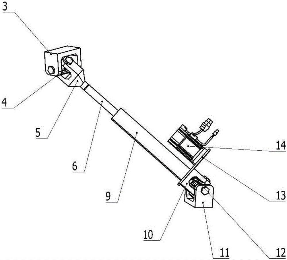
[0025] The first, second, and third branch chains are unconstrained branch chains with six degrees of freedom in space with the same structure, and all contain an actively driven kinematic pair; figure 2 As shown, each branch chain includes: upper connecting piece 3, lower connecting piece 11, upper cross block 4, lower cross block 12, upper U-shaped piece 5, lower U-shaped piece 10, telescopic rod 6, electric cylinder 9 , connecting plate 13, motor 14 and connecting kinematic pair. There are six kinematic pairs, one is a rotating pa...

Embodiment 2

[0032] The structure of a posture adjustment device in this embodiment is as follows: Figure 5As shown, including the moving platform 01, the fixed platform 05 and the first, second and third branch chains, the first, second and third branch chains are unconstrained branch chains with the same structure and six degrees of freedom in space, each containing a Actively driven kinematic pairs; the three branch chains are respectively connected between the moving platform 01 and the fixed platform 05, and form a space closed-loop mechanism with the moving platform 01 and the fixed platform 05. The space parallel closed-loop mechanism moves through three inputs Drive the motion of the moving platform to achieve two rotational degrees of freedom.

[0033] The first, second, and third branched chain structures are the same, such as Figure 6 As shown, each branch chain includes: upper connecting slide rail 010, U-shaped slide block 09, cross block 02, U-shaped piece 08, telescopic r...

Embodiment 3

[0038] The structure of a posture adjustment device in this embodiment is as follows: Figure 8 As shown, it includes the moving platform 001, the fixed platform 008 and the first, second, and third branch chains. The three branch chains are connected between the moving platform 001 and the fixed platform 008 respectively, and are connected The platform 008 constitutes a space closed-loop mechanism.

[0039] The first, second, and third branch chains, such as Figure 9 As shown, all include: upper connecting piece 002, lower connecting piece 009, upper cross block 003, lower shaft pin 0010, upper U-shaped piece 004, lower U-shaped piece 0011, telescopic rod 0012, electric cylinder body 005, connecting plate 007 , motor 006 and motion pair. There are 6 kinematic pairs, one is a rotating pair connected between the upper connecting piece 002 and the upper cross block 003, one is a rotating pair connected between the upper cross block 003 and the upper U-shaped member 004, and t...


PUM


Abstract

The present invention involves a posture adjustment device, which is an automated machinery and equipment design technology field.Including a dynamic flat platform and a fixed platform that installed a actuator, and the three sports branches between the mobile platform and the fixed platform connecting the platform; the three branches are the same space with the same structure.It contains an active driving motion deputy; the link chain connects the setting platform and the dynamic platform to form a space parallel closed -loop mechanism. Through three input motion drive platform motion, the two rotation freedom can be achieved. The present invention has a rigidity.High, bearing capacity, flexible posture adjustment, etc., can effectively prevent the attachment cable equipped on the device from being reversed and damaged.

Description

technical field [0001] The invention belongs to the field of automatic machinery and equipment design, in particular to an attitude adjustment device. Background technique [0002] At present, in many engineering applications such as rotating booths, solar energy utilization, fountain design, stage lighting and radar scanning, there are specific requirements for the spatial posture of actuators. [0003] In the open construction site, large-scale searchlight irradiation supervision is required for multiple key operation objects. For this reason, the utilization rate of searchlights can be improved, the construction cost can be reduced, and a multi-purpose carrying device needs to be developed; in the field of solar energy utilization, solar energy can be collected at different times The attitude of the concentrator relative to the ground will change, and there is an urgent need for the sun tracking function; in the field of airborne radar scanning, there is no report on the ...

Claims


Application Information

Patent Timeline
Patent Type & Authority Applications(China)
IPC IPC(8): B25J9/00B25J19/06
CPCB25J9/0045B25J9/0069B25J19/066
Inventor 刘辛军谢福贵孟齐志梅斌
Owner TSINGHUA UNIV
Why Eureka
Try Eureka